Light-emitting diode assembly
a technology of leds and assemblies, which is applied in the direction of indirect heat exchangers, semiconductor devices of light sources, lighting and heating apparatus, etc., can solve the problems of difficult heat transfer of leds to heat sinks, significantly reducing the lifespan of leds, and reducing heat resistance. , the effect of improving heat transfer efficiency
- Summary
- Abstract
- Description
- Claims
- Application Information
AI Technical Summary
Benefits of technology
Problems solved by technology
Method used
Image
Examples
first embodiment
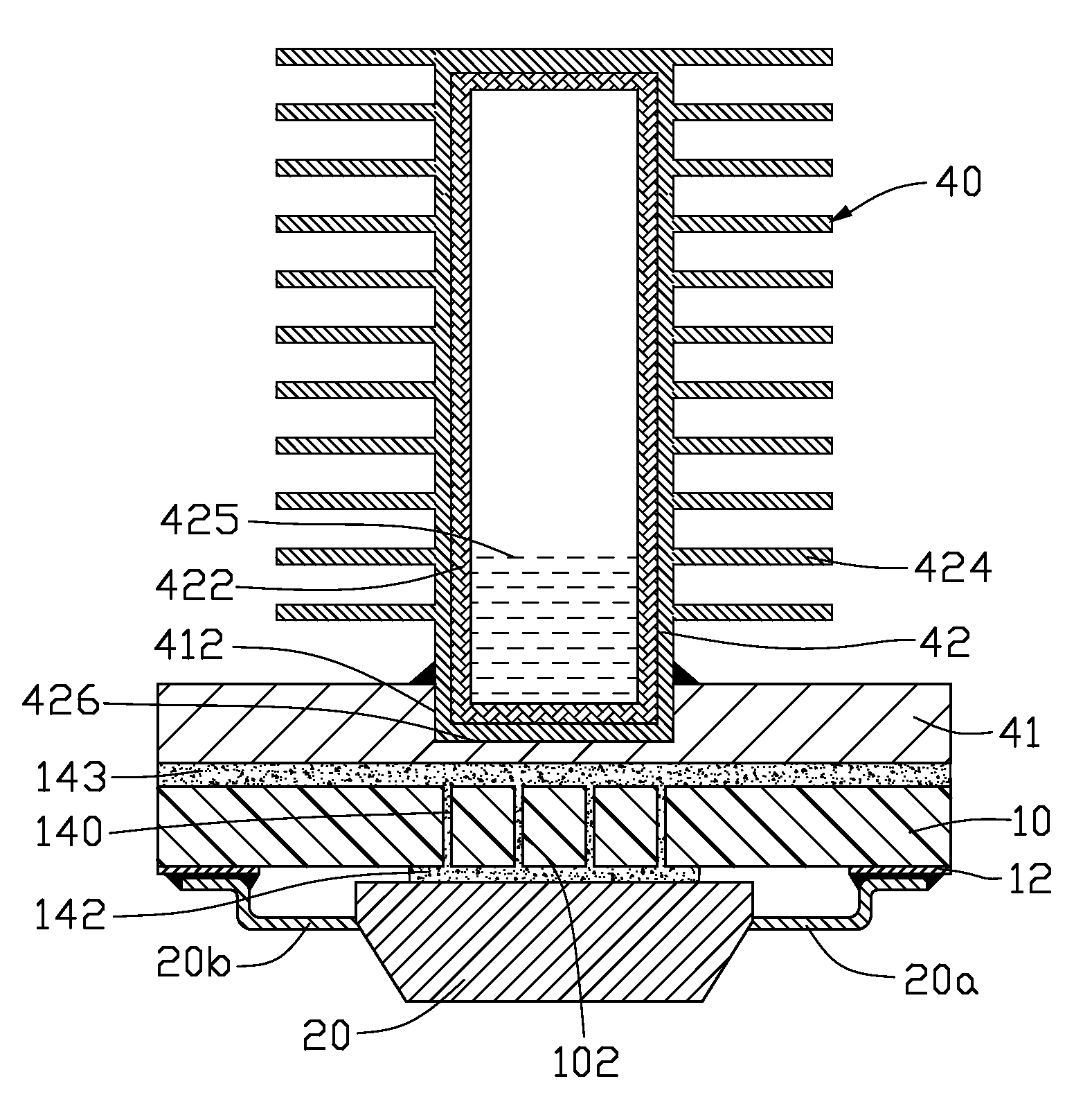
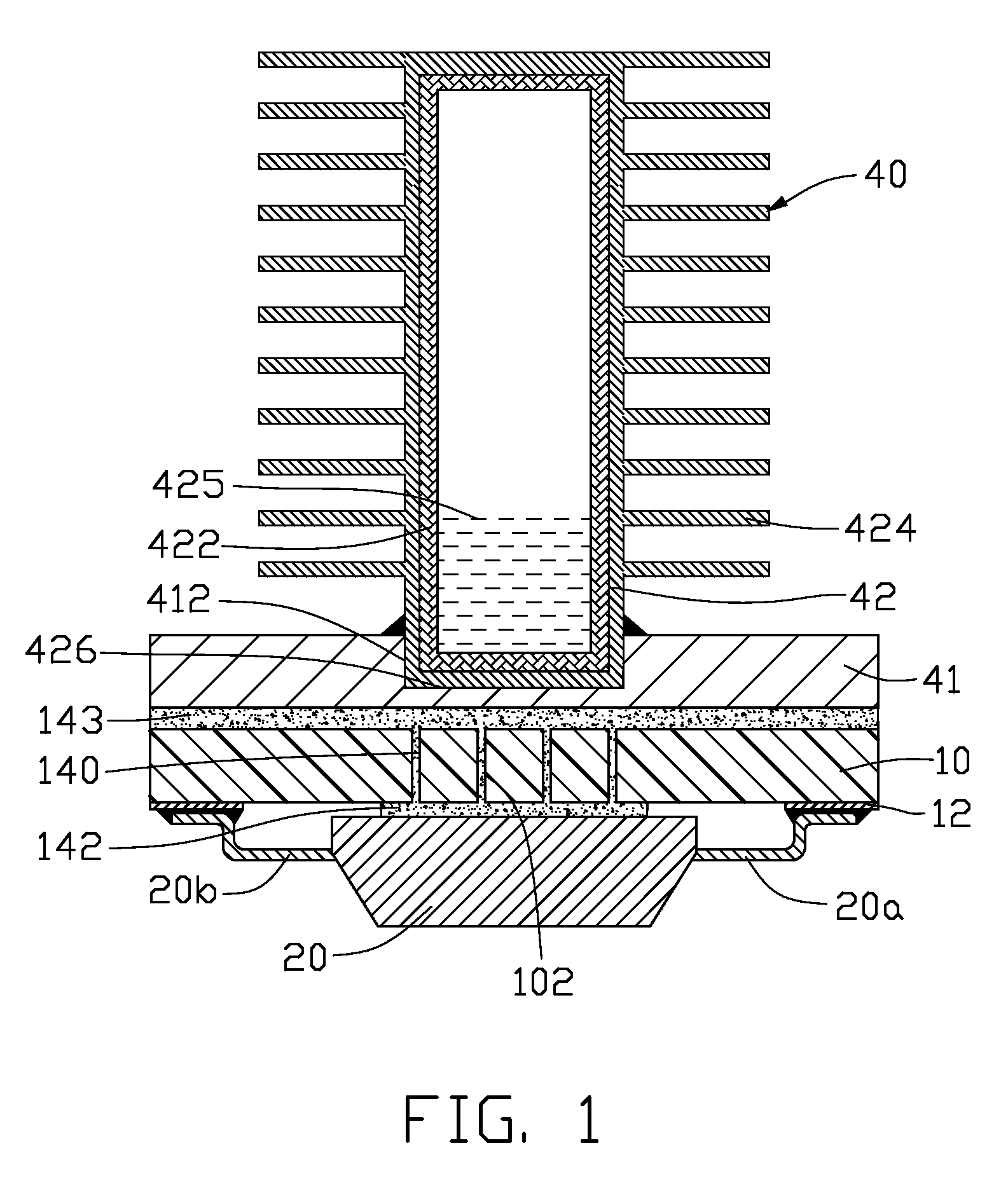
[0017]FIG. 1 illustrates a light-emitting diode (LED) assembly in accordance with the present invention. The LED assembly includes a circuit board 10, an LED 20 arranged on a lower side of the circuit board 10, and a heat dissipation apparatus 40 arranged on an upper side of the circuit board 10.
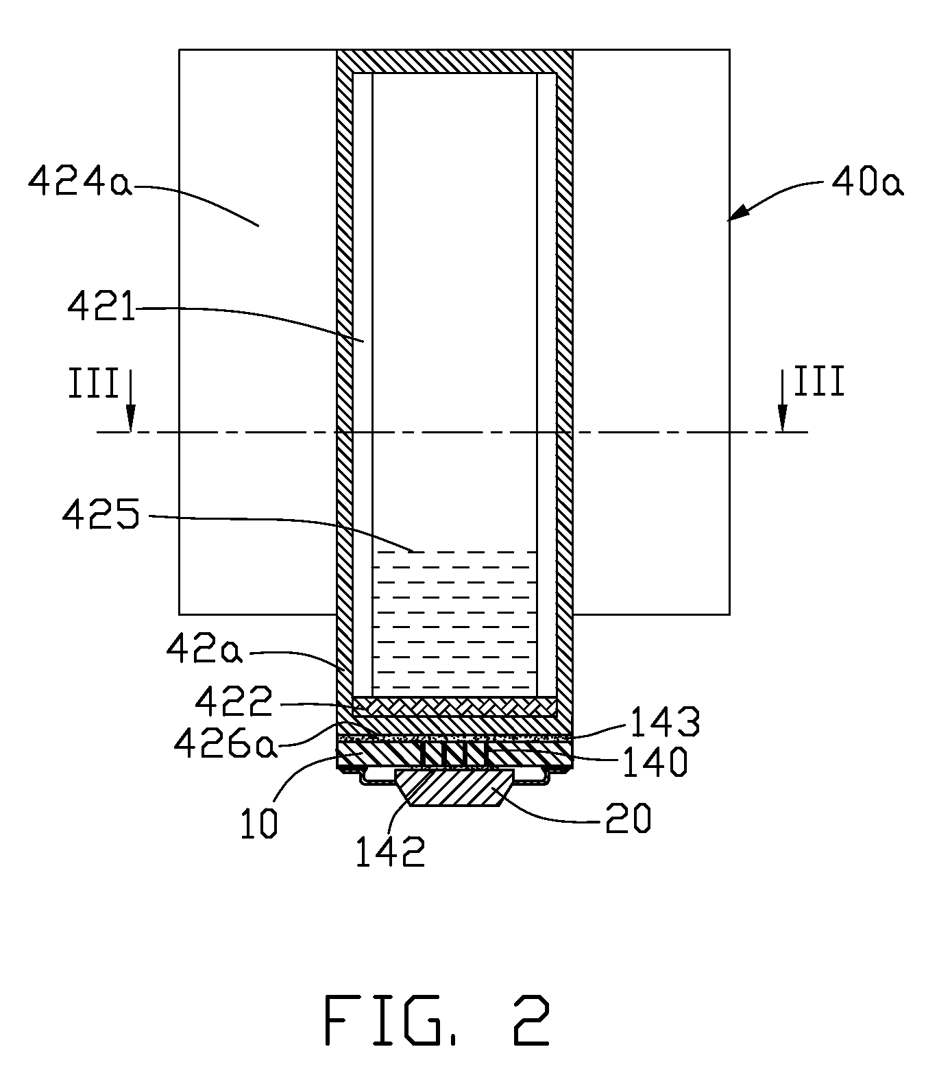
[0018]The circuit board 10 is planar and thin. A circuitry 12 is formed on the lower surface of the circuit board 10. The LED 20 is attached to the lower surface and is electrically connected with the circuitry 12 of the circuit board 10 through wire bonding, in which a pair of gold threads 20a, 20b of the LED 20 is electrically connected with the circuitry 12. Several through holes 102 are defined in the circuit board 10 corresponding to a position of the LED 20. In this embodiment, there are four through holes 102. Alternatively, the number of the through holes 102 can be changed according to a size or a shape of the LED 20 or an amount of heat which will be generated by the LED 20. Each t...
third embodiment
[0025]FIGS. 4-5 show the LED assembly. In this embodiment, the heat pipe 42b of the heat dissipation apparatus 40b is a plate-type heat pipe, and has an elongated, substantially rectangular shape. The bottom surface 428 parallel to the axial direction of the heat pipe 42 is planar-shaped and is thermally attached to the circuit board 10 with the thermally interface material 143 applied therebetween. Since the bottom surface 428 has a much larger area, more LEDs 20 can be mounted on the heat pipe 42b. In this embodiment, there are four LEDs 20 mounted on the heat pipe 42b. Each LED 20 is attached the circuit board 10 thermally and mechanically. The circuit board 10 defines the four through holes 102 corresponding to each LED 20. Also the thermal interface materials 140, 142 are filled in the through holes 102 and applied to the contact surfaces between the LEDs 20 and the circuit board 10, and between the circuit board 10 and the heat pipe 42. The other portion of the outer surface o...
fourth embodiment
[0026]FIGS. 6-7 illustrate the present LED assembly, in which a vapor chamber 42c is provided. The vapor chamber 42c has a much larger size than the heat pipe 42, 42a, 42b shown in the previous embodiments. The vapor chamber 42c has a top surface from which a plurality of fins 424c extend upwardly and a flat bottom surface 428c thermally attached to the circuit board 10. The LEDs 20 are electrically connected with and are maintained in thermal and physical contact with the circuit board 10. The circuit board 10 defines the four through holes 102 corresponding to each LED 20. Also the thermal interface material 140, 142, 143 are filled in the through holes 102, and applied to the contact surfaces between the LEDs 20 and the circuit board 10, and between the circuit board 10 and the bottom surface 428c of the vapor chamber 42c. The vapor chamber 42c also contains a working fluid 425 therein and also employs a phase change mechanism to transfer heat. A plurality of heat transfer enhanc...
PUM
 Abstract
Description
Claims
Application Information
 - R&D
- Intellectual Property
- Life Sciences
- Materials
- Tech Scout
- Unparalleled Data Quality
- Higher Quality Content
- 60% Fewer Hallucinations
Browse by: Latest US Patents, China's latest patents, Technical Efficacy Thesaurus, Application Domain, Technology Topic, Popular Technical Reports.
© 2025 PatSnap. All rights reserved.Legal|Privacy policy|Modern Slavery Act Transparency Statement|Sitemap|About US| Contact US: help@patsnap.com


