Radiation detection apparatus and scintillator panel
a technology of radiation detection apparatus and scintillator, which is applied in the direction of optical radiation measurement, fluorescence/phosphorescence, instruments, etc., can solve the problems of reduced sharpness and achieve the effect of reducing sharpness and increasing light-emission quantity
- Summary
- Abstract
- Description
- Claims
- Application Information
AI Technical Summary
Benefits of technology
Problems solved by technology
Method used
Image
Examples
first embodiment
[0051]A radiation detection apparatus of a first embodiment of the present invention will be described.
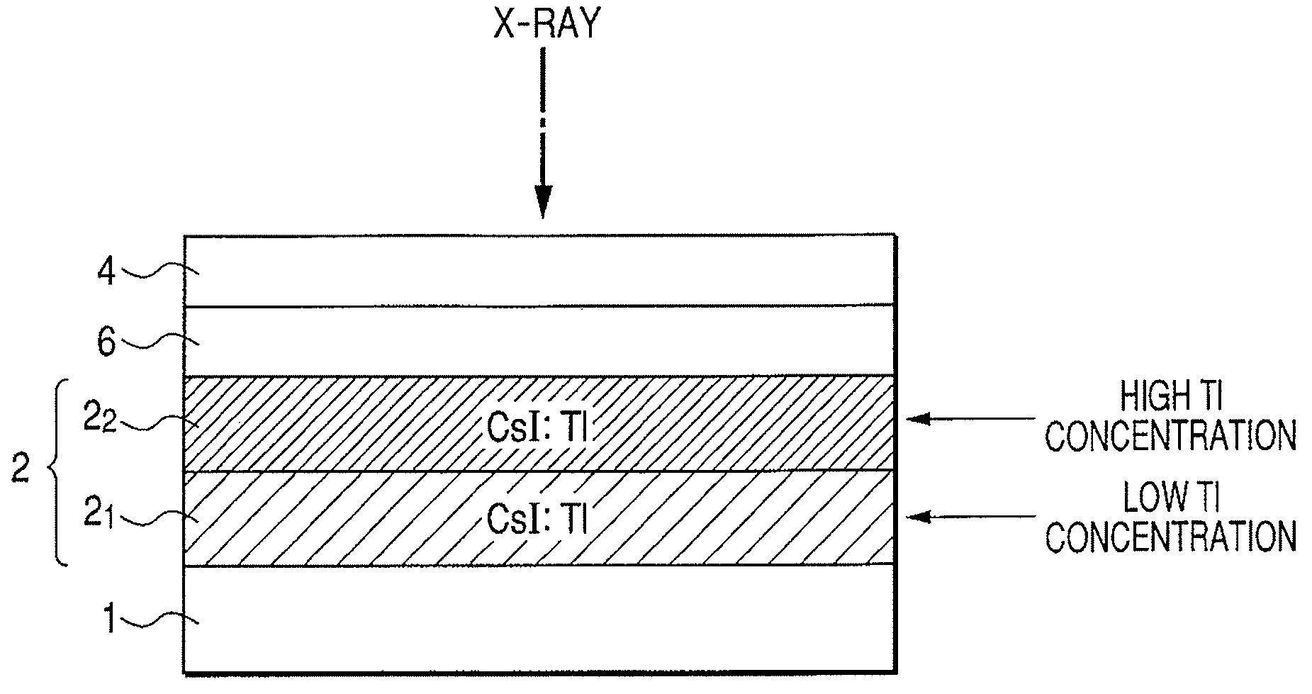
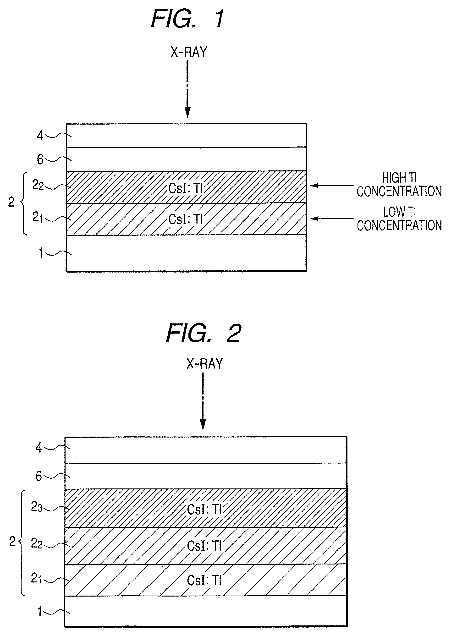
[0052]FIG. 1 is a schematic sectional view of the radiation detection apparatus in the first embodiment.
[0053]The present embodiment is an example on a direct type in which a scintillator layer 2 on a sensor substrate 1 is directly evaporated.
[0054]The sensor substrate 1 is formed with a photoelectric conversion element and a switch element such as TFT, which are two-dimensionally disposed. The sensor substrate 1 is formed with an adhesive layer 6 including scintillator layers 2 (21 and 22), a binding adhesive (such as epoxy resin), a adhesive, a hot melt, and the like, and a protective layer 4 of metal (such as Al, stainless, titanium oxide, and copper alloy). The scintillator layer 2 is an alkaline halide crystal to which has been added an activator such as CsI:Tl and CsI:Na. The protective layer 4 doubles as a reflecting layer for reflecting light from the scintillator layer 2. ...
second embodiment
[0082]A radiation detection apparatus of a second embodiment of the present invention will be described.
[0083]FIG. 4 is a schematic sectional view of the radiation detection apparatus in the second embodiment.
[0084]The present embodiment is an example on an indirect type, in which a scintillator layer 2 is evaporated on a substrate 5, and after that, it is adhered to a sensor substrate 1 through an adhesive layer 6. An embodiment which forms the scintillator layer 2 on the substrate 5 can be taken as a scintillator panel.
[0085]The substrate 5 made of amorphous carbon (“a-C”) and the like is formed with a reflecting layer 3 of metal (such as Al, stainless, titanium oxide, and copper alloy), a scintillator layer 2 made of CsI and the like, and a protective layer 4 made of polyparaxylene, hotmelt and the like. These layers are adhered to a sensor substrate 1 having the same configuration as in the first embodiment through an adhesive layer 6 made of a binding adhesive (such as epoxy re...
third embodiment
[0096]FIG. 7 is a schematic sectional view of a radiation detection apparatus in a third embodiment.
[0097]The present embodiment is an example of a direct type in which a scintillator layer 2 on a sensor substrate 1 is directly evaporated. A sensor substrate 1, an adhesive layer 6, and a protective layer 4 are the same as those of the first embodiment.
[0098]In the present embodiment, for the scintillator layer 2, thallium (Tl) is used as an activator, and its concentration is distributed so as to be gradually changed. That is, the concentration of the activator is given a distribution such that the concentration is gradually lowered from the radiation-incident side to the optical detector side.
[0099]Next, a method for producing the scintillator layer of the radiation detection apparatus illustrated in the present embodiment will be described.
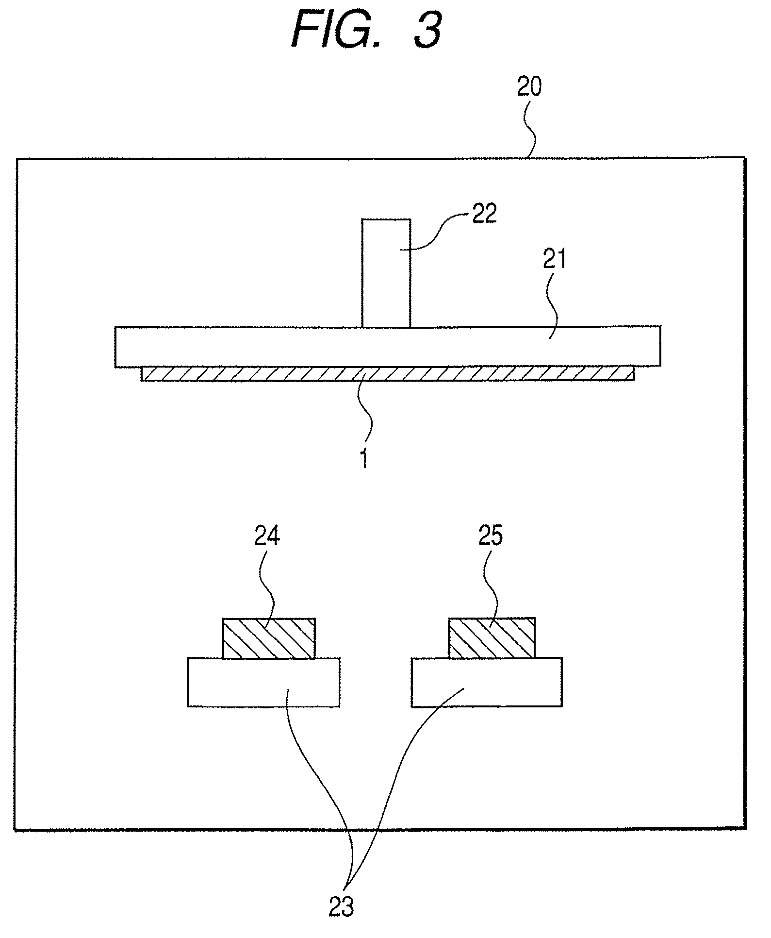
[0100]The method for producing the radiation detection apparatus of the present embodiment uses the vacuum vapor deposition apparatus illustrat...
PUM
 Abstract
Description
Claims
Application Information
 - R&D
- Intellectual Property
- Life Sciences
- Materials
- Tech Scout
- Unparalleled Data Quality
- Higher Quality Content
- 60% Fewer Hallucinations
Browse by: Latest US Patents, China's latest patents, Technical Efficacy Thesaurus, Application Domain, Technology Topic, Popular Technical Reports.
© 2025 PatSnap. All rights reserved.Legal|Privacy policy|Modern Slavery Act Transparency Statement|Sitemap|About US| Contact US: help@patsnap.com


