
Monolithic microchip laser with intracavity beam combining and sum frequency or difference frequency mixing

a microchip laser and intracavity beam technology, applied in the direction of laser details, optical resonator shape and construction, instruments, etc., can solve the problems of long-term reliability problems, large laser cost, and inefficient, and achieve compact and cost-effective manner, suppressing unwanted polarization, and high-volume manufacturing

Active Publication Date: 2009-05-19
PAVILION INTEGRATION
View PDF26 Cites 28 Cited by
  • Summary
  • Abstract
  • Description
  • Claims
  • Application Information

AI Technical Summary

Benefits of technology

"The present invention provides a method and apparatus for generating low-noise laser beams from a monolithic microchip laser using intracavity beam combining and frequency conversion. The invention allows for the generation of various laser wavelengths, including blue, green, and orange lasers, with high efficiency and low optical noise. The invention also allows for the use of a single gain medium or two independent gain media, as well as the inclusion of optical elements for specific applications. The invention further includes a compact and efficient monolithic structure that can be fabricated and tested for high-volume manufacturing. The invention also provides a solution for generating laser beams with desired bandwidths and polarization directions. Overall, the invention provides a more flexible and effective method for generating high-quality laser beams from a monolithic microchip laser."

Problems solved by technology

As a consequence, traditional air-cooled Argon ion lasers, HeNe lasers, and dye lasers, though bulky and inefficient, have been the workhorse for the past years and are still playing important roles in these spectral ranges.
However, these lasers are generally expensive and may have long-term reliability issues, especially when costly waveguide materials are employed.
However, these systems generally have shortcomings of complicated structure, high loss, and unstable operation.
In addition, the achievable wavelengths in dual-wavelength lasers are limited to transitions with similar stimulated emission cross sections.
The drawbacks of these devices include intracavity loss due to insertion of wavelength separating plates and stringent coating requirements.
It is difficult to create and maintain population inversion in such a system when a strong transition, e.g. 4F3 / 2→4I11 / 2, is present in the same medium.
However, their architectures are complicated, requiring many optical components, and the efficiency is low.
Other challenges for intracavity frequency doubled lasers or intracavity SFM lasers include reduction of optical noises such as amplitude fluctuations in the green output caused by nonlinear interactions of the longitudinal modes.
All of these approaches require the insertion of mode-selection elements and / or temperature stabilization or a long resonator, introducing additional complexity and cost.

Method used


Image

  • Monolithic microchip laser with intracavity beam combining and sum frequency or difference frequency mixing
  • Monolithic microchip laser with intracavity beam combining and sum frequency or difference frequency mixing
  • Monolithic microchip laser with intracavity beam combining and sum frequency or difference frequency mixing

Examples


example 1

Monolithic Microchip Laser for Generating 491.7 nm Light

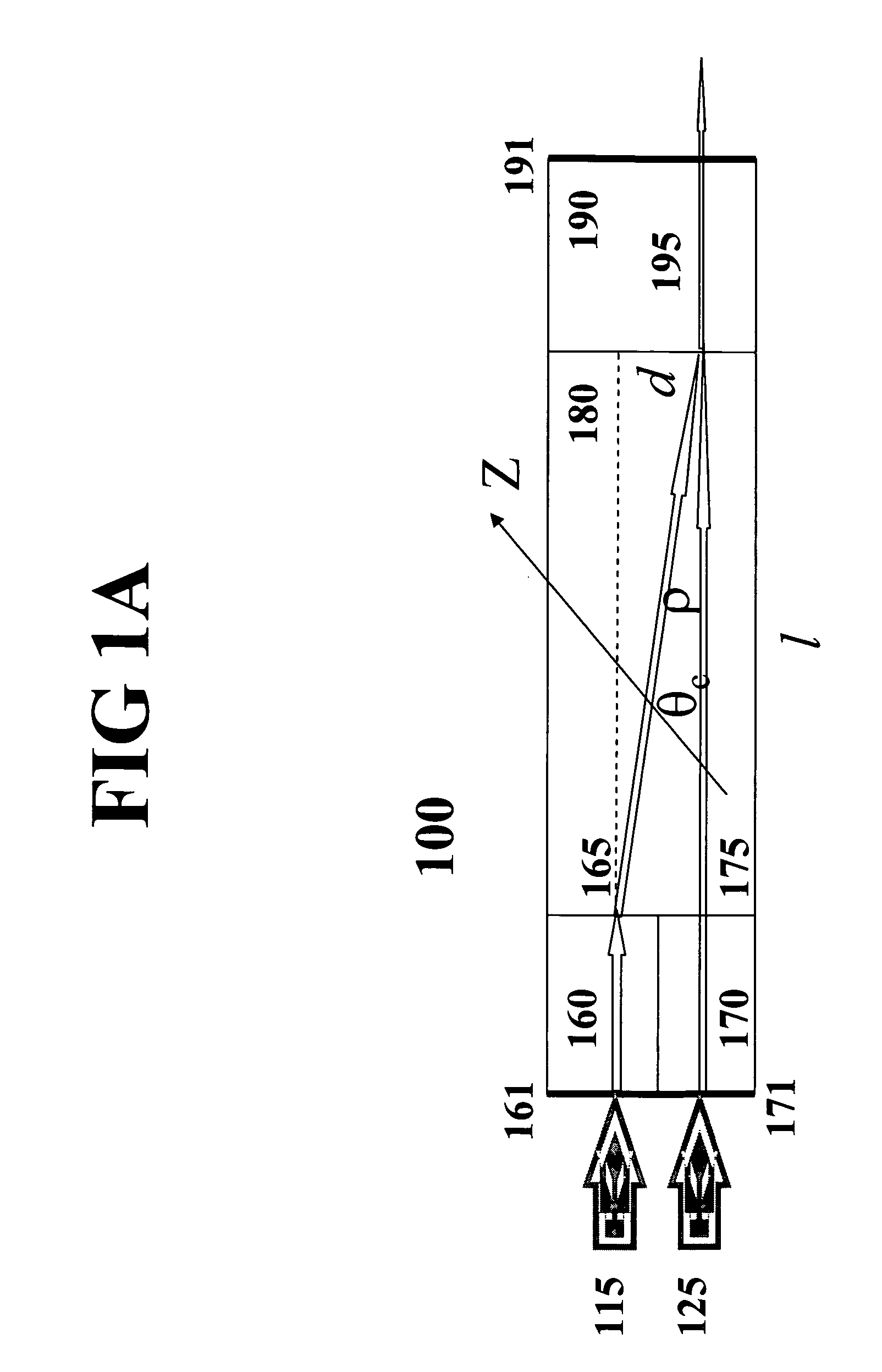
[0076]Returning to FIG. 1A. In this specific example, the monolithic microchip laser 100 consists of two independent pumping sources 115 and 125, two Nd:YVO4 laser gain media 160 and 170, a birefringent crystal such as un-doped YVO4 or TiO2 180, and a nonlinear crystal KTP 190. These crystals are optically bonded and in physical contact for elimination of the boundary optical loss in generation of intracavity SFM or DFM.

[0077]In a preferred embodiment, the pumping lights 115 and 125 are output from a build-in dual-emitter diode laser that emits two individual laser beams, but can also from two separate emitter diode lasers, depending on specific applications. Each emitter can have a 1 μm×50 μm aperture and emit upto 500 mW power output at 808 nm or have 1 μm×200 μm aperture and emit upto 2 W power output at 808 nm or other aperture size to emit an appropriate power. These two emitters are separated each other with a preferable ...

example 2

Monolithic Microchip Laser for Generating 593.5 nm Light

[0082]Continuing in reference to FIG. 1A. With modification of some parameters, the same configuration can be applied to other wavelength conversion devices, e.g., 593.5 nm lasers. These parameters include proper selection of mirror coatings and KTP phase matching angle.

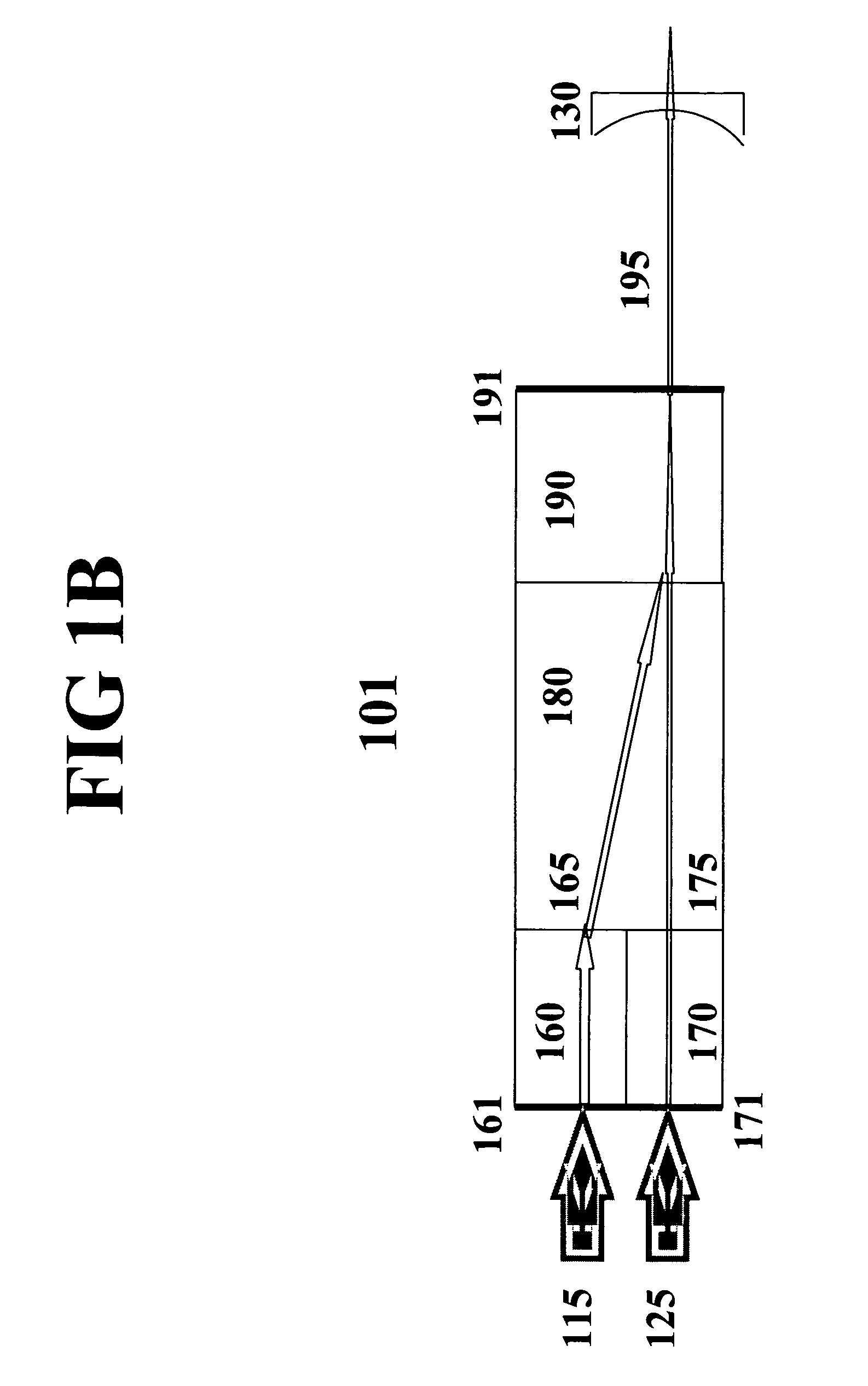
[0083]In order to generate laser output at 593.5 nm, the coating 161 should be highly reflective at 1064 nm and highly transmissive (T>95%) at 808 nm. Similarly, the mirror 171 is coated HR at 1342 nm and HT at 808 nm. The coating 171 is also HT at 1064 nm to prevent this high-gain transition from lasing. The coating 191 on the exterior surface of microchip 100 is HT at 593.5 nm, and HR at both 1342 and 1064 nm. In some applications, configurations illustrated in FIG. 1B or 1C or 1E or 1F can be used.

[0084]FIG. 3B shows a flowchart of the wavelength conversion. Advantageously, an algorithm for automatic power control enables individual adjustment of pumping powe...


PUM


Abstract

A method for producing low-noise laser output at various wavelengths and / or in various operation modes in a monolithic microchip laser comprises schemes of generating two fundamental beams in separate cavities, precise intracavity beam combination based on the walk-off effect in birefringent crystal, and wavelength conversion in nonlinear optical crystals. The fundamental beams are produced from light sources selected upon the desired wavelengths, polarizations, and other features related to the laser output. Low-noise laser devices operated in SLM or with spectra of flat-top or desired bandwidths are constructed according to the method. High-volume fabrication is feasible. Apparatus of compact size and efficient frequency conversion is demonstrated with various configurations including those for generating low-noise 491 nm laser, as a replacement of Argon ion laser.

Description

CROSS REFERENCE TO RELATED APPLICATION[0001]This application claims the benefit of U.S. Provisional Application No. 60 / 663,503, filed Mar. 18, 2005, and U.S. Provisional Application No. 60 / 708,596, filed Aug. 15, 2005, which are hereby incorporated by reference in its entirety.FIELD OF THE INVENTION[0002]This invention relates generally to solid-state lasers, and in particular to monolithic microchip lasers using intracavity beam combining and sum frequency mixing (SFM) or difference frequency mixing (DFM) to generate a variety of lasing wavelengths including 457 nm, 473 nm, 491 nm, 505 nm, 532 nm, and 593 nm with low optical noise.BACKGROUND OF THE INVENTION[0003]Continuous-wave (CW) monochromatic lights at a number of wavelengths such as blue (λ˜490 nm) and orange (λ˜590 nm), which are useful for scientific research and medical or industry applications, cannot be directly generated from a laser diode or diode-pumped solid-state (DPSS) laser. As a consequence, traditional air-coole...

Claims


Application Information

Patent Timeline
Patent Type & Authority Patents(United States)
IPC IPC(8): H01S3/10H01S3/08
CPCG02F1/3534H01S3/0627H01S3/07H01S3/0811H01S3/09415H01S3/108H01S3/1083H01S3/109G02F1/3544H01S3/005H01S3/0405H01S3/0602H01S3/0604H01S3/0612H01S3/08H01S3/08054H01S3/08086H01S3/0809H01S3/082H01S3/1611H01S3/1643H01S3/1673H01S3/2383H01S2302/00
Inventor LUO, NINGYIZHU, SHENG-BAILU, SHAOPING
Owner PAVILION INTEGRATION
Learn More