
Electromagnetic interference shield and heat sink apparatus

a technology of electromagnetic interference shield and heat sink, which is applied in the direction of electrical apparatus casing/cabinet/drawer, casing/cabinet/drawer details, instruments, etc., can solve the problems of unenclosed portion of pod card, noise of fans, and cost prohibitive tooling of metal rails

Inactive Publication Date: 2009-05-05
MAGNOLIA LICENSING LLC
View PDF9 Cites 5 Cited by
  • Summary
  • Abstract
  • Description
  • Claims
  • Application Information

AI Technical Summary

Benefits of technology

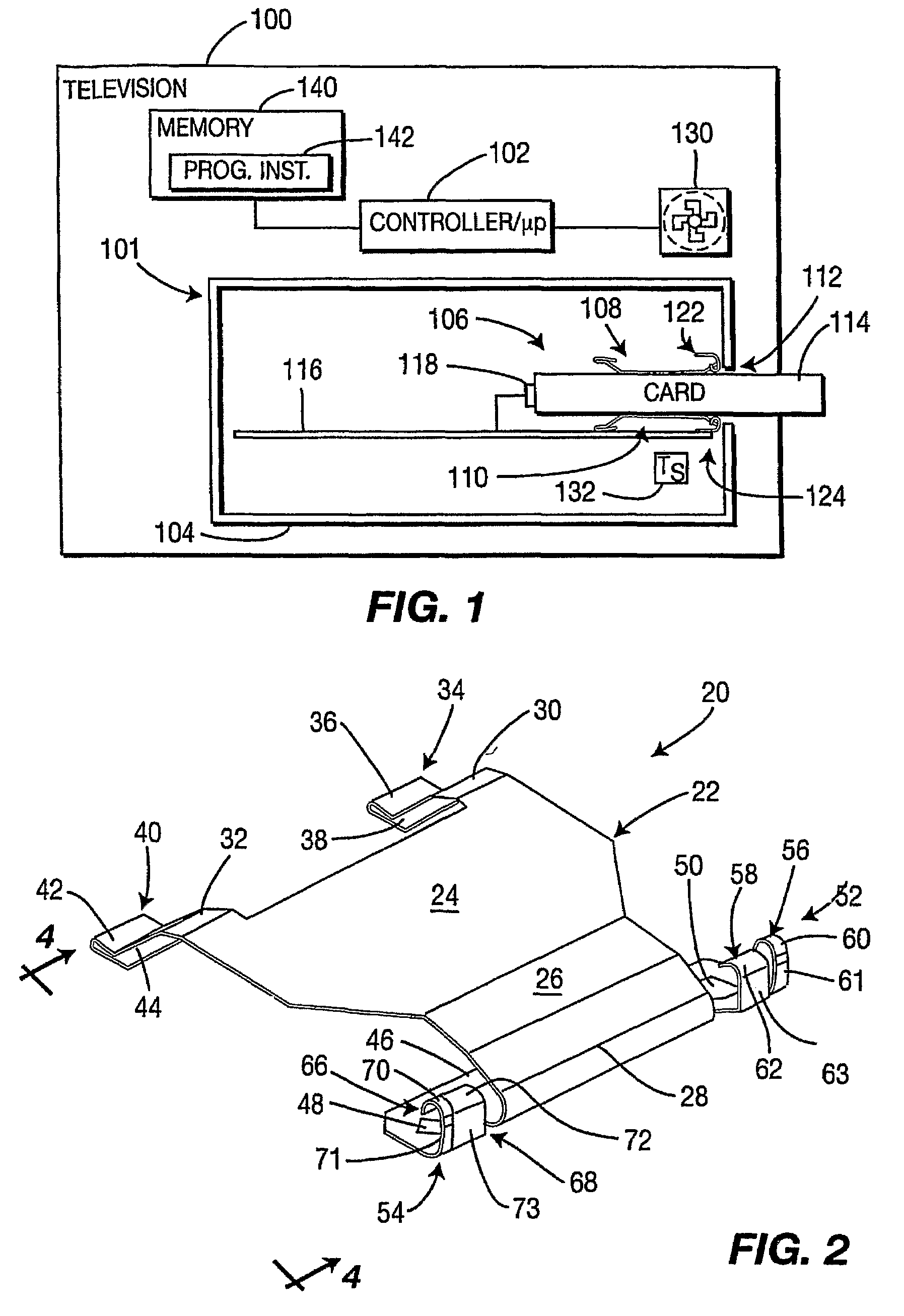
"The invention provides a combination heat sink and electromagnetic interference shield for a point of distribution (POD) card. This eliminates the need for a fan at room temperatures and provides EMI shielding of a portion of the POD card that extends beyond a metal enclosure or wrap of a POD control module. The combined heat sink and electromagnetic interference shield provide a low impedance connection between the POD card and the surrounding module metalwork of the television, which reduces or eliminates EMI. The device includes a POD card guide portion and a combined thermal transfer and electromagnetic conduction portion that provides thermal and electromagnetic coupling between the inserted POD card and metalwork of the television. The technical effect is improved thermal management and EMI shielding for the POD card."

Problems solved by technology

While this is not a significant problem for the portion of the POD card enclosed in the metalwork of the television chassis, an additional problem exists with respect to the unenclosed portion of the POD card as discovered by the present inventors and shown from various radiation tests.
The cost of tooling such metal rails, however, is currently cost prohibitive.
While a fan could be used for cooling the POD card, the main disadvantage of a fan is the noise.
Many televisions are used in places where such fan noise would be considered unacceptable.
Although functional, tooling costs and complexity of the door is not an acceptable solution.

Method used


Image

  • Electromagnetic interference shield and heat sink apparatus
  • Electromagnetic interference shield and heat sink apparatus
  • Electromagnetic interference shield and heat sink apparatus

Examples


Embodiment Construction

[0027]The embodiment disclosed herein is not intended to be exhaustive or limit the invention to the precise form disclosed so that others skilled in the art may utilize its teaching.

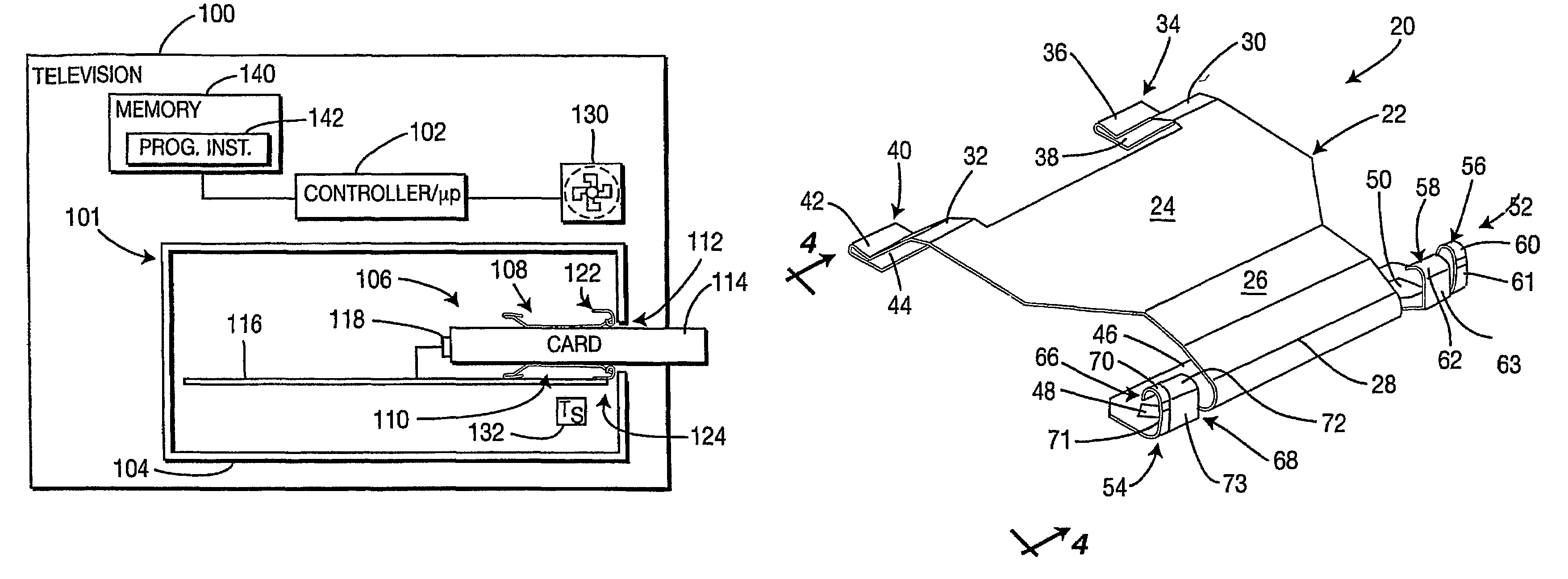
[0028]FIG. 1 illustrates an exemplary television receiver, generally designated 100. The television receiver 100 represents various types of devices that receive and process television signals but is particularly representative of a television. More particularly, the television receiver 100 is representative of a digital cable-ready television. It should be appreciated, however, that the present invention is applicable to all types of television receivers and as well to other electronic devices that utilize integrated circuit cards such as Point of Distribution (POD) cards, smart cards, PCMCIA cards, and the like. It should be appreciated that the term POD card refers to all types of integrated circuit cards and cards comprising electronic circuitry such as are used in televisions, particularly such as ...


PUM


Abstract

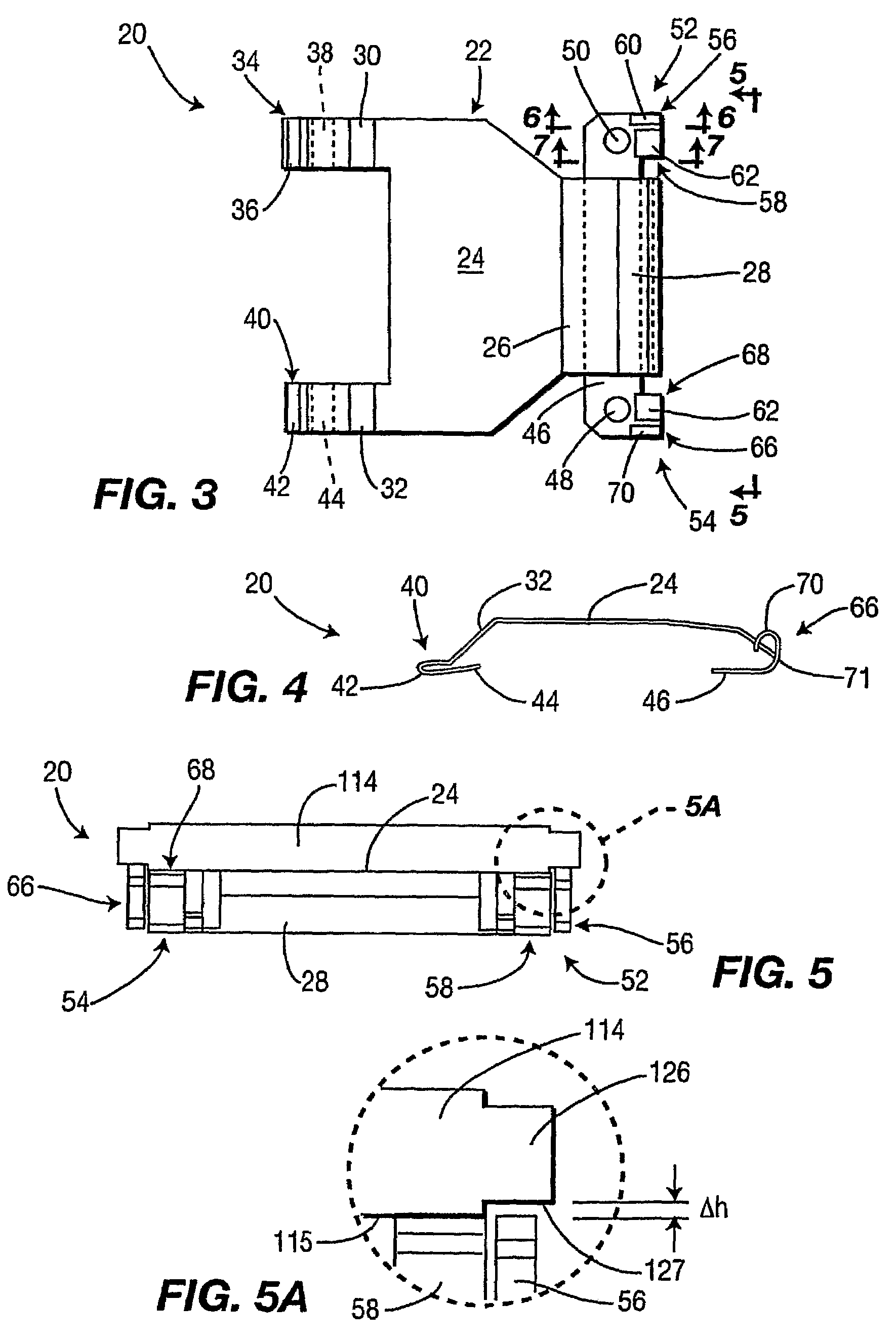
A combination heat sink and electromagnetic interference shield device is provided for a point of distribution card of a television receiver. The combination POD card heat sink and EMI shield device includes a combined thermal transfer and electromagnetic conduction portion that provides thermal and EM coupling or contact between an enclosure of the POD card and the metal control module enclosure of a television. Configured metalwork of the combination heat sink and EMI shield device provides conduction of heat from the POD card to provide the heat sink and short circuiting of developed currents to provide EMI shielding. The combined thermal transfer and EM conduction portion provides a low impedance connection between the POD card and the surrounding module metalwork of the television. This low impedance path provides a short for circulating current in the exposed metalwork that diminishes or essentially eliminates EMI. The present invention allows a POD card to operate at room temperature without the need for a cooling fan through the heat sink metalwork.

Description

[0001]This application claims the benefit, under 35 U.S.C. § 365 of International Application PCT / US2004 / 042492, filed Dec. 15, 2004, which was published in accordance with PCT Article 21(2) on Nov. 10, 2005 in English and which claims the benefit of U.S. provisional patent application No. 60 / 533,325, filed Apr. 15, 2004.BACKGROUND OF THE INVENTION[0002]1. Field of the Invention[0003]The present invention relates to the field of television receivers and, more particularly, to the use of point of distribution cards in television receivers.[0004]2. Background Information[0005]Starting in 2004, regulations require all television receivers (televisions) that want to carry a “Digital Cable Ready” label indicating that the television receiver is capable of receiving and decoding various digital cable television formats, must incorporate what is known as a Point of Distribution (POD) card. A POD card is similar to a smart card or PCMCIA card, such as are used in satellite television receiv...

Claims


Application Information

Patent Timeline
Patent Type & Authority Patents(United States)
IPC IPC(8): H05K7/20F28F7/00H04L9/00H05K5/02H05K9/00
CPCG06F1/182G06F1/185G06F1/20H05K5/0286H05K7/20445H05K9/0016H05K9/0018
Inventor TESTIN, WILLIAM JOHNROTTLER, SCOTT ALLEN
Owner MAGNOLIA LICENSING LLC
Learn More