
Processor, processor system, temperature estimation device, information processing device, and temperature estimation method

a technology of processors and temperature estimation devices, applied in the field of processors, can solve problems such as poor time response, chip malfunction or long-term reliability drop, and chip temperature partially becoming abnormally high

Active Publication Date: 2009-04-21
SONY COMPUTER ENTERTAINMENT INC
View PDF7 Cites 25 Cited by
  • Summary
  • Abstract
  • Description
  • Claims
  • Application Information

AI Technical Summary

Benefits of technology

[0008]The present invention has been achieved in view of the foregoing problem. Thus, a general purpose of the present invention is to provide a processor, a processor system, an information processing apparatus, and a temperature estimation method capable of grasping the temperatures at locations of heat generation accurately.
[0019]Still another embodiment of the present invention also relates to a temperature estimation method. This method comprises: applying a random load to a processor; measuring differences between a temperature of a certain block of the processor detected by a sensor and temperatures of a plurality of heat generating blocks of the processor; determining estimation errors in estimating the temperatures of the plurality of heat generating blocks from the detected temperature; and adjusting a position of the certain block for the sensor to detect the temperature thereof, so that the estimation errors become relatively smaller.

Problems solved by technology

Chips can malfunction or drop in long-term reliability when at high temperatures.
Moreover, uneven distribution of power consumption over a chip inevitably produces the problem of so-called “hot spots,” or that the chip partially becomes abnormally high in temperature.
This means poor time response.
As above, since highly-integrated processors cause a plurality of hot spots in places, it has been difficult to grasp the temperatures of the hot spots with a single temperature sensor accurately.

Method used


Image

  • Processor, processor system, temperature estimation device, information processing device, and temperature estimation method
  • Processor, processor system, temperature estimation device, information processing device, and temperature estimation method
  • Processor, processor system, temperature estimation device, information processing device, and temperature estimation method

Examples


Embodiment Construction

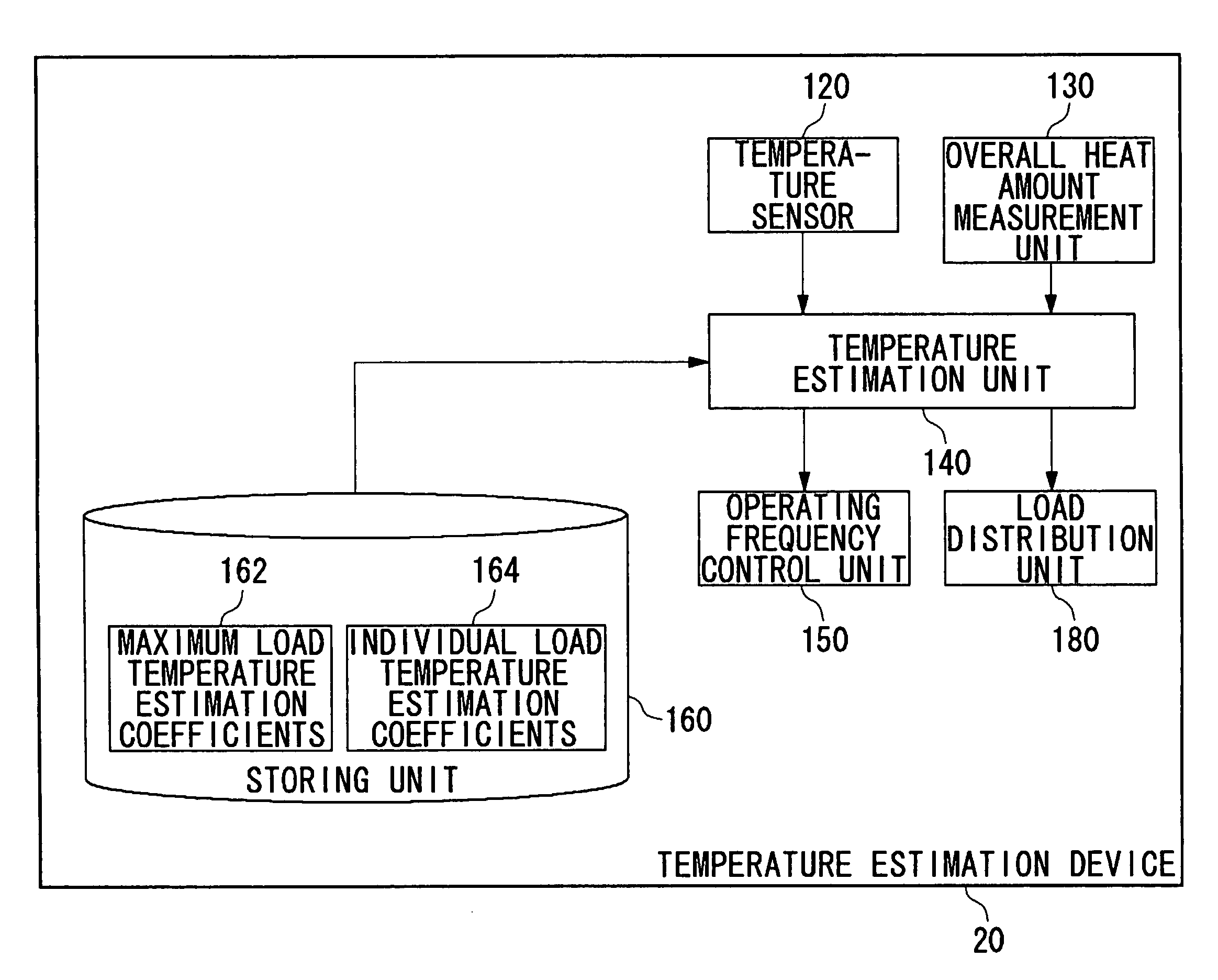
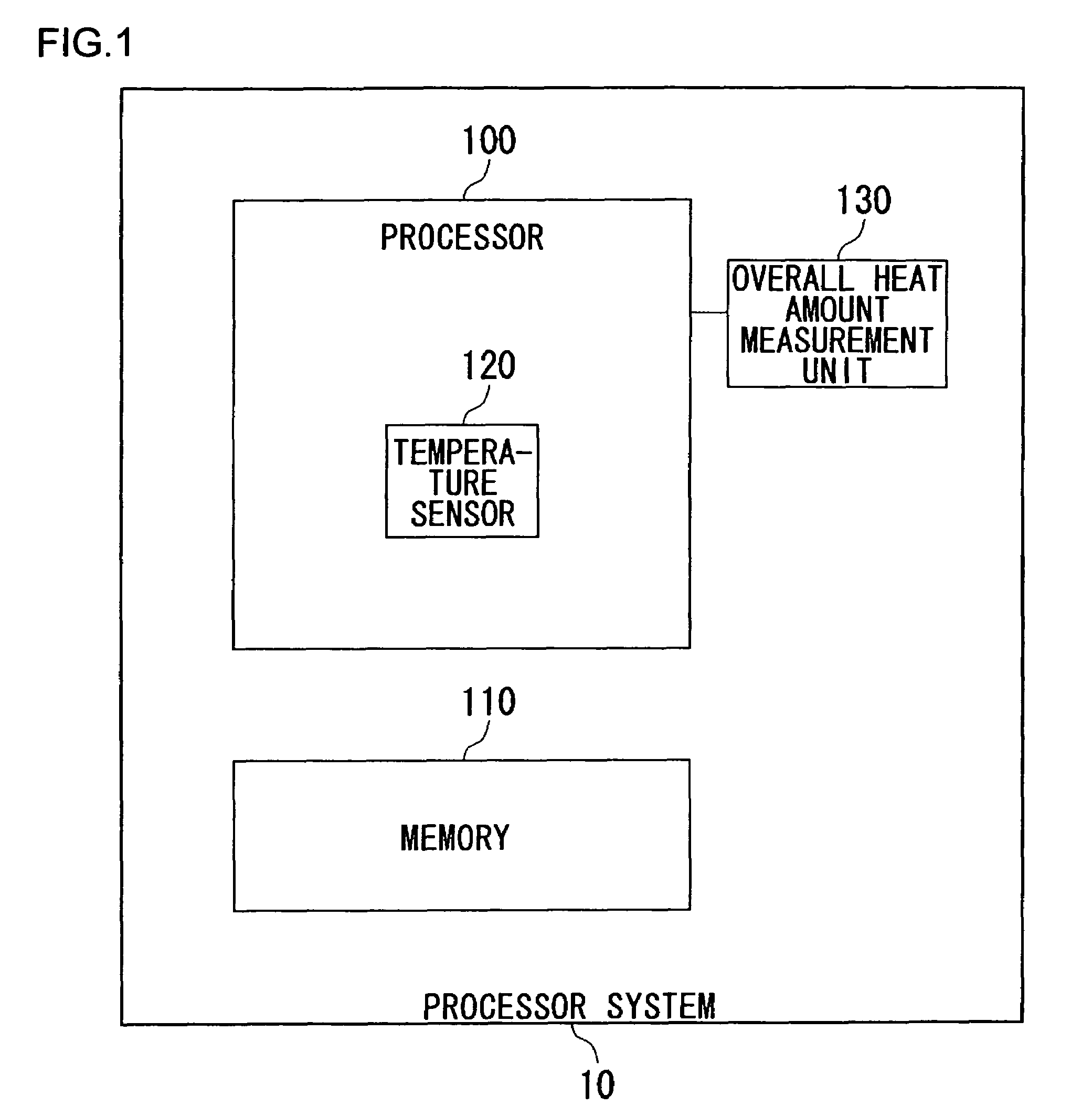
[0034]FIG. 1 is a block diagram of a processor system 10 according to an embodiment of the invention. The processor system 10 includes a processor 100 and a memory 110, which are connected with a bus. The processor 100 is provided with a temperature sensor 120 for measuring the temperature inside the device. The temperature sensor 120 is formed directly on the die on the top of the package of the processor 100, and measures the temperature of a certain location inside the processor 100.

[0035]An overall heat amount measurement unit 130 is formed outside the processor 100, and measures the overall amount of heat of the processor 100. The overall heat amount measurement unit 130 is a temperature sensor which uses a heat sink or the like of the processor 100. When a heat sink or other component having an extremely high heat capacity is placed on the chip, it is possible to measure the average amount of heat of the processor 100. To measure the amount of heat of the processor 100 more ac...


PUM

PropertyMeasurementUnit
temperatureaaaaaaaaaa

Abstract

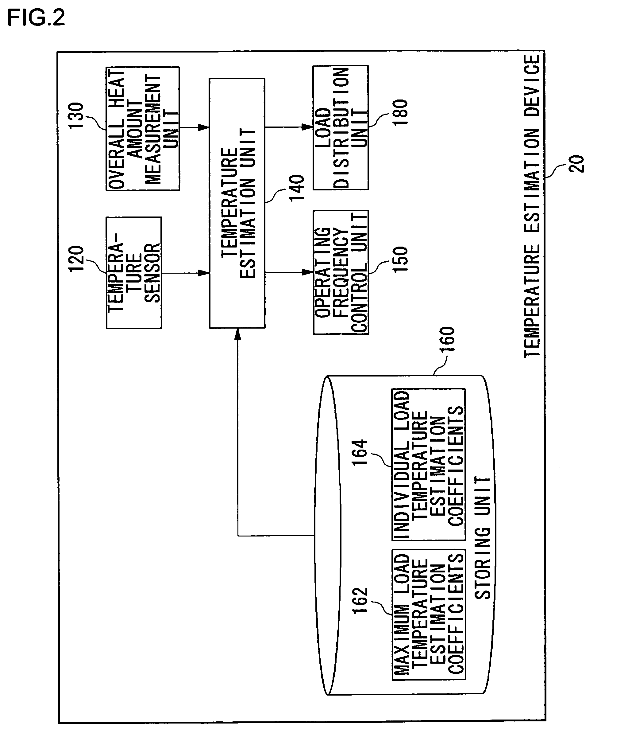
A temperature sensor measures a temperature of a certain location inside a processor. An overall heat amount measurement unit measures the overall amount of heat of the processor. A temperature estimation unit estimates the temperatures of a plurality of hot spots occurring in the processor based on the temperature of the certain location detected by the temperature sensor, and determines the maximum temperature of the processor. The temperature estimation unit switches between maximum load temperature estimation coefficients and individual load temperature estimation coefficients stored in a storing unit for reference, depending on the overall amount of heat of the processor, and applies them to a temperature estimation function(s) for converting the sensor temperature into the temperatures of the hot spots. An operating frequency control unit exercises control for lowering the operating frequency of the processor when the maximum temperature of the processor estimated by the temperature estimation unit exceeds a predetermined limit temperature.

Description

BACKGROUND[0001]1. Technical Field[0002]The invention relates to processor technologies, and more particularly to a processor, a processor system, a temperature estimation device, an information processing apparatus, and a temperature estimation method capable of estimating the temperature inside the processor.[0003]2. Related Art[0004]With increasing trends of LSI design toward finer manufacturing processes and higher device integration, it is becoming extremely important, in terms of design, to give consideration to the amount of heat generation as chips' performance limits. Chips can malfunction or drop in long-term reliability when at high temperatures. Various measures against heat generation have thus been taken. For example, in one method, radiating fins are arranged on the top of a chip so as to radiate heat occurring from the chip.[0005]Moreover, uneven distribution of power consumption over a chip inevitably produces the problem of so-called “hot spots,” or that the chip p...

Claims


Application Information

Patent Timeline
Patent Type & Authority Patents(United States)
IPC IPC(8): G01K1/00G01K7/00G06F19/00G06F1/04G06F1/20G06F1/32
CPCG06F1/206G06F1/3203G06F1/324Y02D10/00G06F1/20G06F1/32
Inventor YAZAWA, KAZUAKITAKIGUCHI, IWAOIMAI, ATSUHIKOTAMURA, TETSUJIADACHI, KENICHI
Owner SONY COMPUTER ENTERTAINMENT INC
Learn More