
Abnormality detection method and abnormality detection system for operating body

a technology of abnormality detection and operating body, which is applied in the direction of testing/monitoring control systems, instruments, nuclear elements, etc., can solve the problems of failure of products, failure of operating bodies, and failure to perform predetermined operations

Inactive Publication Date: 2010-07-22
HITACHI CABLE
View PDF8 Cites 32 Cited by
  • Summary
  • Abstract
  • Description
  • Claims
  • Application Information

AI Technical Summary

Benefits of technology

[0011]Under these circumstances, in order to address the above problems, it is an objective of the present invention to provide an abnormality detection method and an abnormality detection system for an operating body, by which even when the degrees of abnormality or monitoring signals change due to external effects, the progress of the abnormality can be accurately grasped and thereby the abnormality can be precisely detected by eliminating the external effects.

Problems solved by technology

When, however, an operating body is placed in long-time continuous operation or members in individual sections of the operating part are deteriorated by disturbance, the operating body may stop operating or may not perform predetermined operations.
Other possible problems involved are that safety is not assured and failures are found in the products.

Method used


Image

  • Abnormality detection method and abnormality detection system for operating body
  • Abnormality detection method and abnormality detection system for operating body
  • Abnormality detection method and abnormality detection system for operating body

Examples


first embodiment

of the Invention

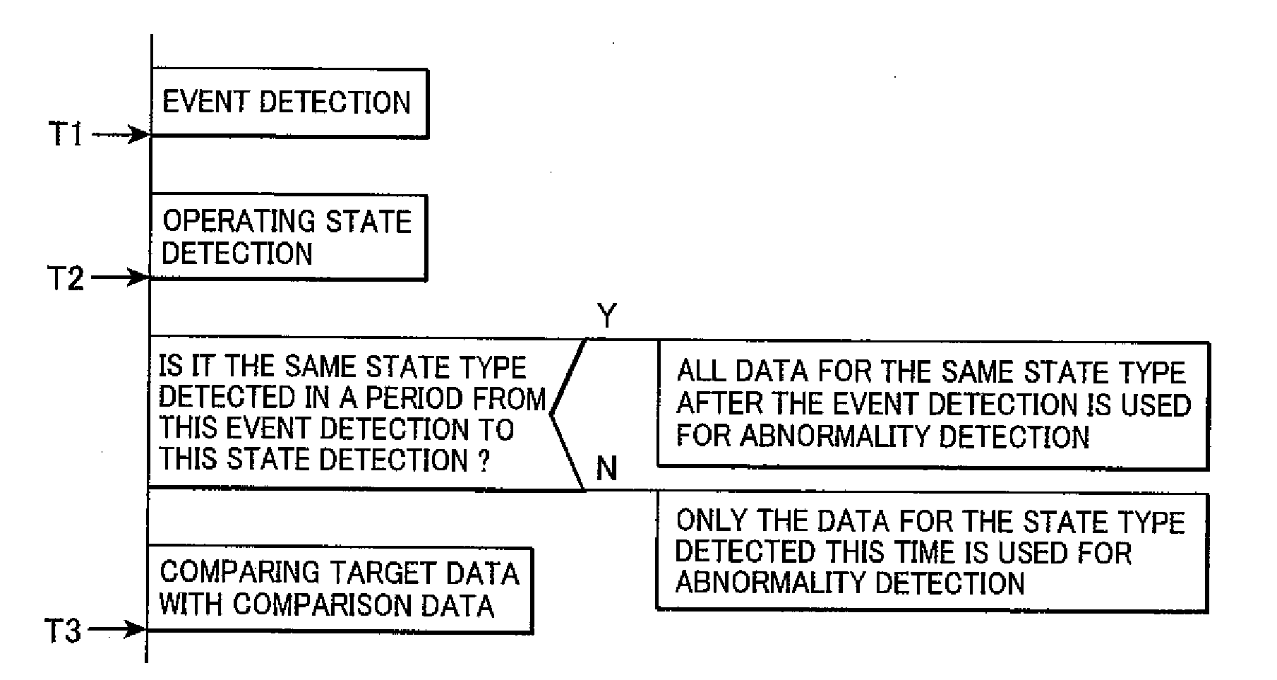
[0045]In a novel method of detecting abnormality in an operating body 1 according to the present invention, data on the operating body 1 is continuously collected; events for the operating body 1 are detected; the data collected in a predetermined period delimited by these events is extracted as target data; the target data is compared with comparison data which is prepared in advance for abnormality detection; and abnormality in the operating body 1 is detected from the comparison result.

[0046]The data is any type of monitoring signal which can be used for detection of an abnormality or events and can also be used for state determination as described later. The data includes output signals indicating physical quantities detected by physical quantity sensors and control signals used to control the operating body by, e.g., manipulations.

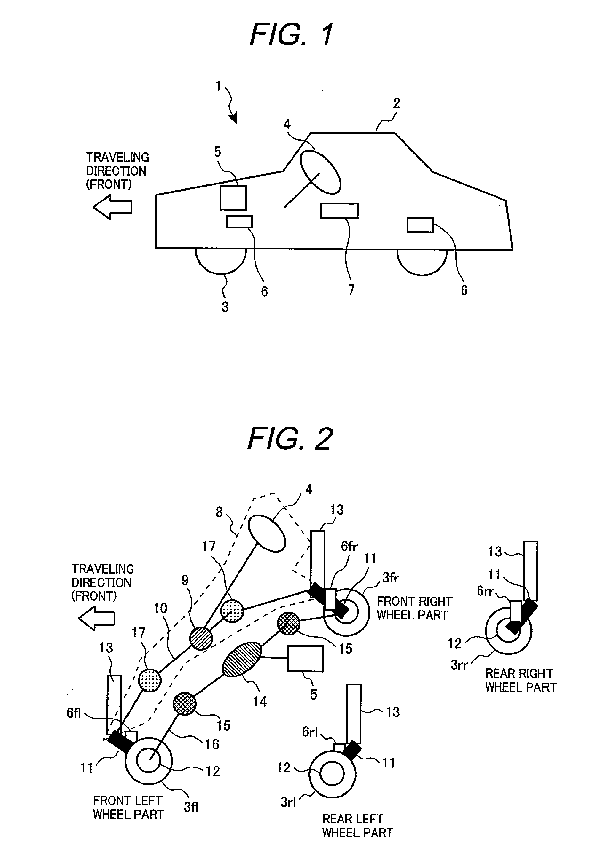
[0047]If the operating body 1 is an automobile, the data includes: velocity, acceleration, vibration, sound, angular velocity, member...

second embodiment

of the Invention

[0122]Another embodiment of the present invention will be described below.

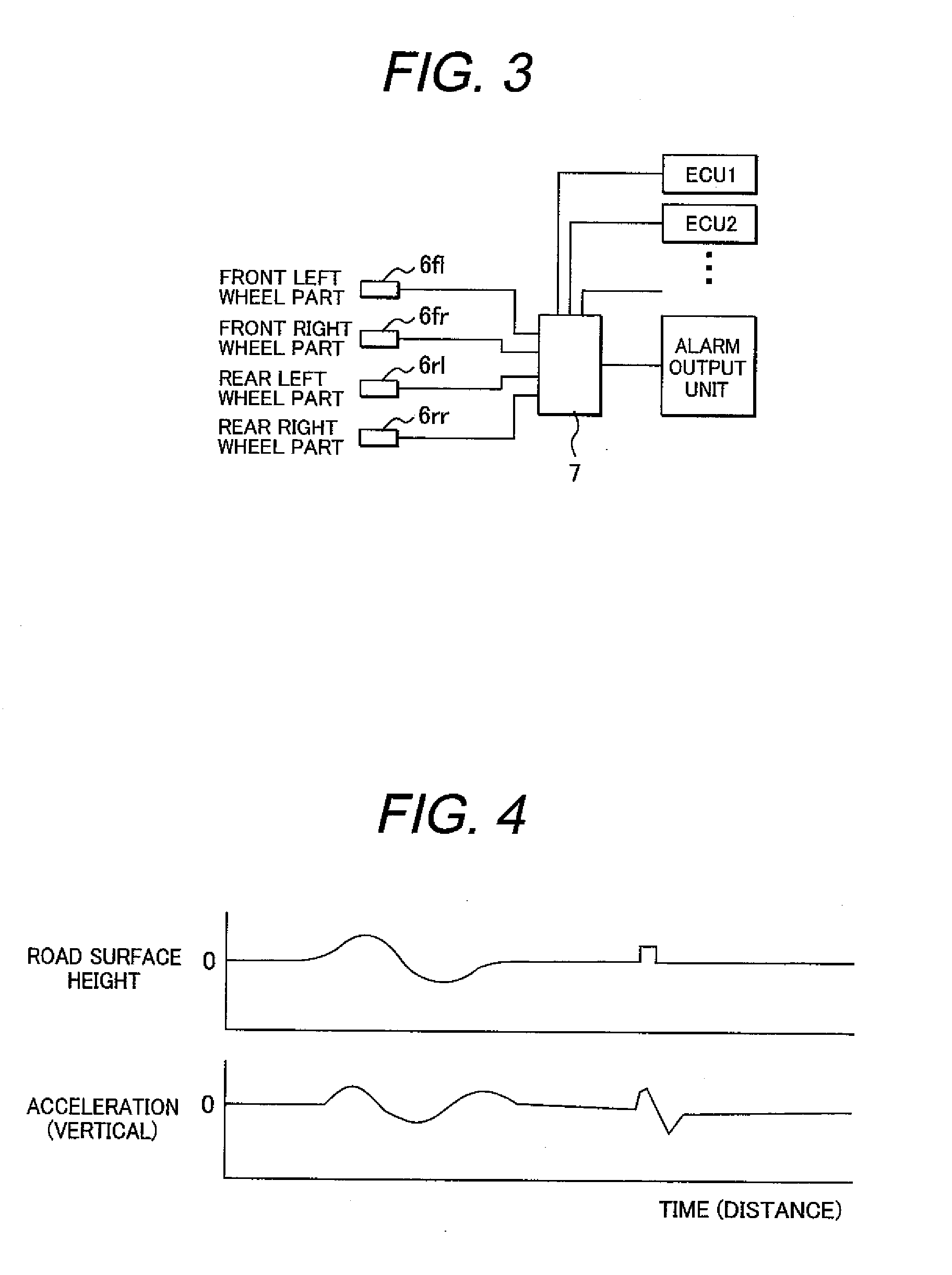
[0123]In the case that the operating body 1 is an automobile, monitoring signals (output signals from the acceleration sensors 6, for example) may be classified into signals synchronous with the rotation of the wheel 3 and asynchronous signals. The rotational speed (angular speed) of each wheel 3 can be detected from the output pulse generated by, e.g., a wheel rotation sensor attached near the wheel 3 for an antilock braking system (ABS). The rotational speed of the wheel 3 can also be detected by counting the number of output pulses generated by the wheel rotation sensor for one turn of the wheel 3. The number of output pulses generated from the wheel rotation sensor for one turn of the wheel 3 depends on the design of the wheel rotation sensor. It is preferable to classify the monitoring signals into signals synchronous with the rotation of the wheel 3 and asynchronous signals according to t...


PUM


Abstract

A method of detecting an abnormality in an operating body, according to the present invention, comprises steps of: continuously collecting data about the operating body; detecting events for the operating body; extracting part of the data as target data, the part of the data being collected in a predetermined period delimited by times at which the events are detected; preparing comparison data in advance for abnormality detection; comparing the target data with the comparison data to obtain a comparison result; and detecting an abnormality in the operating body from the comparison result.

Description

CLAIM OF PRIORITY[0001]The present application claims priority from Japanese patent application serial no. 2009-007958 filed on Jan. 16, 2009, the content of which is hereby incorporated by reference into this application.BACKGROUND OF THE INVENTION[0002]1. Field of the Invention[0003]The present invention relates to an abnormality detection method and abnormality detection system, particularly to an abnormality detection method and abnormality detection system for an operating body in which the degrees of abnormality or monitoring signals of the operating body are fluctuated by external effects.[0004]2. Description of Related Art[0005]First of all, in this specification, moving bodies, such as automobiles and trains, and manufacturing apparatuses used to perform various types of processing for raw materials, such as wire twisting, extrusion, and rolling, are collectively referred to as operating bodies. Operating bodies are preferably designed so that they can withstand continuous ...

Claims


Application Information

Patent Timeline
IPC IPC(8): G06F15/00G01M99/00
CPCB60W50/0205B60W50/04G05B23/021G05B23/0224
Inventor YAMAMOTO, SATOSHI
Owner HITACHI CABLE
Learn More