
Radiation homing tag

a homing tag and radio frequency technology, applied in the field of armaments, can solve the problems of inability to provide ground combat units with platforms and delivery systems, inaccurate direct-fire rifles, and expensive vehicular platforms, and achieve the effect of increasing the munitions rang

Active Publication Date: 2009-03-17
BAE SYST INFORMATION & ELECTRONICS SYST INTERGRATION INC
View PDF35 Cites 25 Cited by
  • Summary
  • Abstract
  • Description
  • Claims
  • Application Information

AI Technical Summary

Benefits of technology

[0013]The present invention is a tag for use in guiding munitions. The tag includes at least one emitting radiator which is modulated by means of a code at a specific frequency. A processing gain is thereby obtained which affords an increased munitions range.
[0014]Various types of radiators are possible today. A light emitting diode (LED) provides for low-cost, high conversion efficiency optical designation. A laser diode can further increase optical gain by selectively emitting energy in a narrow band, further reducing the effects of background radiation clutter. Efficiencies of laser diodes are improving, and an infrared (IR) diode would be compatible with the current inventory of optically guided munitions. Lastly, a radio-frequency emitter could be used with modulation gain, although RF guided munitions in the present military arsenal are just emerging.
[0015]A further aspect of the invention is to provide a homing tag which is integrated into a small rugged aerodynamic-shaped body formed of a material which houses the electronics including the emitter(s), which body has sufficient strength to protect the components from shock, and which provides acceptable levels of radiation transmittance. A preferable embodiment for an optical homing tag would be in a polymer housing transparent in the infrared (IR) frequency band selected for optimum signal-to-background clutter performance.

Problems solved by technology

Large guided munitions have been successfully developed and deployed but have generally required expensive vehicular platforms (fixed wing or rotary aircraft) or large caliber guns (ships or mobile howitzers) to deliver the munitions.
These platforms and delivery systems may not be available to ground combat units, whose speed, mobility and agility contribute to their survivability.
Rifles are accurate direct-fire weapons, but challenging to integrate guidance or homing tags due to their small caliber (typically 5.66 mm or 223 caliber).
But they lack the volume to carry sufficient explosives to effect large areas or hardened targets.
One of the major disadvantages of mortars is their comparatively low accuracy, and as a result mortars are becoming less effective in today's precision combat environment.
Unguided munitions are subject to aim error and wind disturbances.
These factors, along with other more subtle error sources, may cause the munition to miss the target completely or require many rounds to complete the fire mission due to the resulting large CEP (Circular Error Probability).
Current approaches to guided weapons are expensive and are used on larger, long range weapons.
Mortars are typically unguided or guided by an expensive G&C (Guidance and Control) system.
The cost is high for current guided mortars and unguided mortars may have poor accuracy.
Also, unguided mortars may result in unacceptable collateral damage, excess cost due to the large number of rounds required to blanket the target area, and may expose the mortar crew to counterbattery fire due to the large time required to drop the necessary shells to saturate the target.
Although these various types of optical designators are satisfactory in certain respects, they have certain drawbacks in that it requires a forward observer to be close enough to the target to place the optical designator on the target such as by a laser beam, and requires that he has possession of the needed equipment.
Also, this placement requires that the forward observer be close to the target which could alert the enemy at the target site of his presence and also result in injury to the forward observer.
Thirdly, the forward observer must designate the target for a period of time, making themselves in turn open to detection or hostile attack.
Other methods would require the need to have a plane in the air near the target, which again would alert the enemy at the target of an attack, possibly resulting in countermeasures being exerted on the forward observer and / or plane.
It is difficult to secretly place an optical designator at the target which would remain undetected by the occupants of the target until the munition is ready to be launched.

Method used


Image

  • Radiation homing tag
  • Radiation homing tag
  • Radiation homing tag

Examples


Embodiment Construction

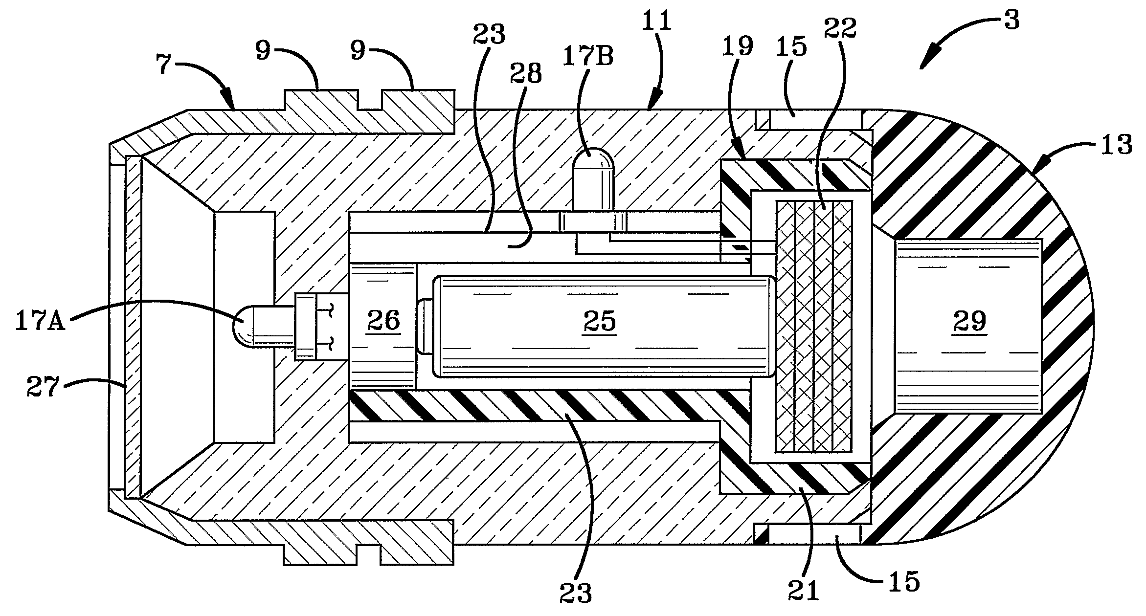
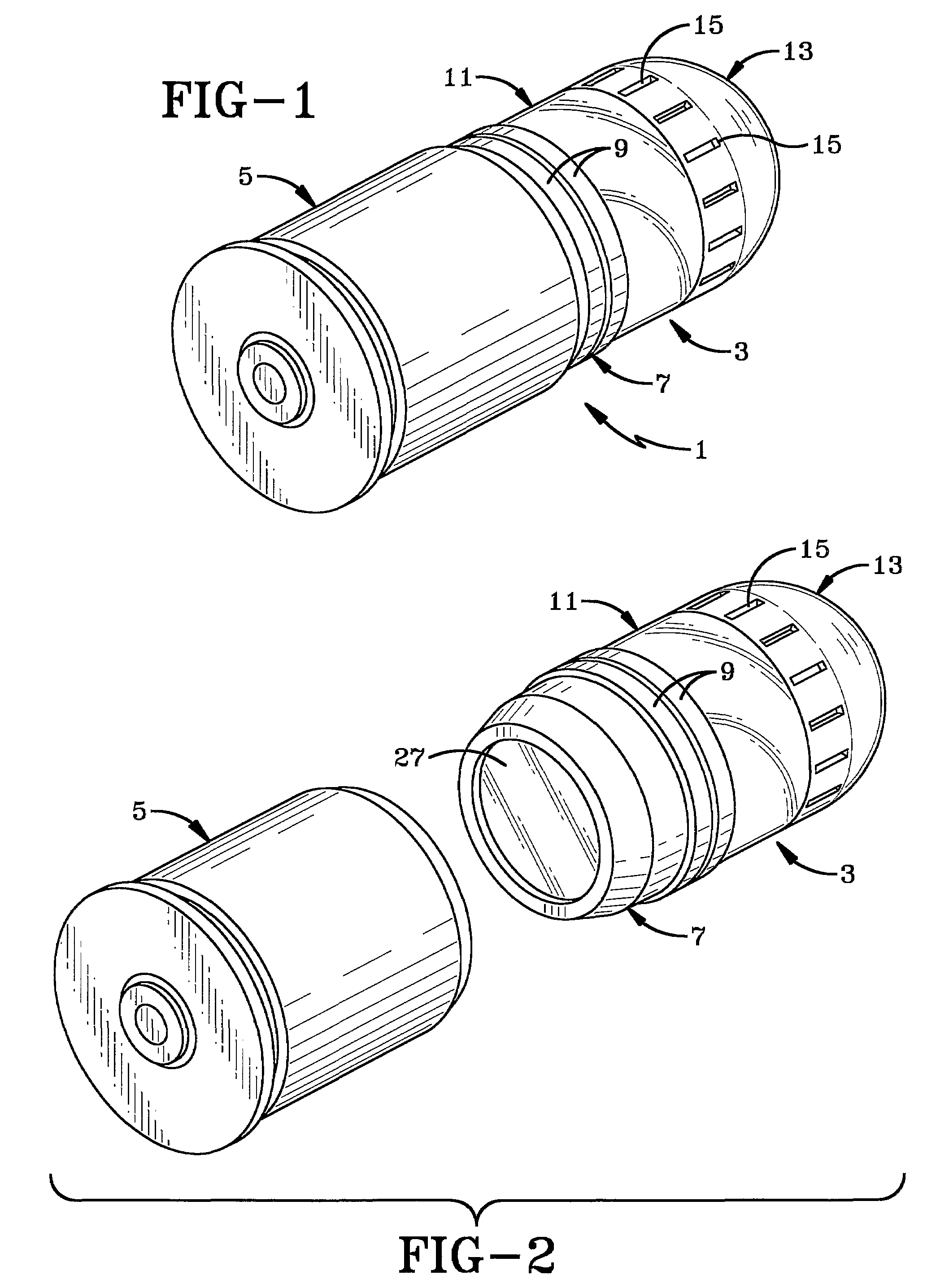
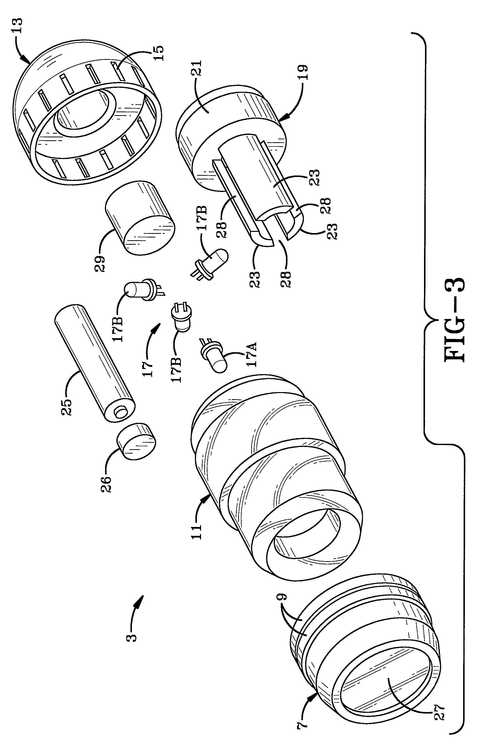
[0028]The optical version of a homing tag which is the preferred embodiment of the present invention is indicated generally at 1, and is intended to be placed near or on a target position, in one instance as a 40 mm grenade as shown in FIG. 1. Optical homing tag 1 includes a transmissive housing indicated generally at 3, which is attached to a cartridge case 5, which contains an impulse charge for propelling the optical housing to a target. The housing includes an aft body 7 to provide an interface with the cartridge case 5, typically by a crimp joint. Rotating bands 9 are located at a leading edge of aft body 7 which enables the optical housing to engage the riflings of a barrel when used with certain types of launch equipment, providing an aerodynamic spin to the housing as it leaves the barrel of the launcher to ensure proper flight dynamics. The boat tail design of aft body 7 as shown in FIG. 3, minimizes aerodynamic drag as the optical housing moves through the air toward a tar...


PUM


Abstract

The homing tag (1) has a transmissive housing (3), which is attached to a cartridge case (5). The transmissive housing (3) includes an aft body (7) to provide an interface with the cartridge case (5). Rotating bands (9) are located at a leading edge of the aft body (7). The transmissive housing (3) further includes a central body (11). The ogive-shaped nose (13) is formed of transparent material. A pluralit of slots (15) are provided for cooling the transmissive housing (3).

Description

CROSS REFERENCE TO RELATED APPLICATION[0001]This application claims rights under 35 USC 119(e) from U.S. application Ser. No. 60 / 650,709, filed Feb. 7, 2005; the contents of which are incorporated herein by reference.BACKGROUND OF THE INVENTION[0002]1. Field of the Invention[0003]The present invention relates to armaments and more particularly to guided munitions. Even more particular, the invention relates to an optical homing tag for guiding the muntions to a target.[0004]2. Background Information[0005]Mortars and other forms of indirect munition fire are one of the most commonly employed weapons in a ground combat unit. Large guided munitions have been successfully developed and deployed but have generally required expensive vehicular platforms (fixed wing or rotary aircraft) or large caliber guns (ships or mobile howitzers) to deliver the munitions. These platforms and delivery systems may not be available to ground combat units, whose speed, mobility and agility contribute to t...

Claims


Application Information

Patent Timeline
Patent Type & Authority Patents(United States)
IPC IPC(8): F41G7/00F42B15/01G01S1/00F42B15/00G01S13/00
CPCF41G3/18F41G7/226F41G7/2293F42B12/365F42B12/40G01S1/70G01S1/7034
Inventor MAYNARD, JOHN A.ORTOLF, JAMES M.CARLSON, MARK A.ZEMANY, PAUL D.
Owner BAE SYST INFORMATION & ELECTRONICS SYST INTERGRATION INC
Learn More