Process for producing and applying a laser heat transfer capable of printing on flat, cylindrical, curved, and irregularly shaped objects

a technology of laser heat transfer and laser heat transfer, which is applied in the field of printing on flat, cylindrical, curved or irregular surfaces, can solve the problem that no other process is available, and achieve the effects of low cost, high potential and simple process

Active Publication Date: 2009-02-24
POKALLUS KEVIN
View PDF23 Cites 5 Cited by
  • Summary
  • Abstract
  • Description
  • Claims
  • Application Information

AI Technical Summary

Benefits of technology

[0037](1) The laser heat transfer process is very cost effective. The cost of the equipment is very reasonable, and the cost of the image carrier material and laser toner supplies is considerably less than that of a conventional heat transfer for low to medium volume applications. Also, the laser heat transfer process does not seem to damage or degrade certain carrier materials. By using such materials several times, or even indefinitely, it is possible to virtually eliminate recurring carrier costs.
[0038](2) The laser heat transfer process is simple. By purchasing pre-coated carrier material which is compatible with a conventional laser printer, it is unnecessary to pre-treat the carrier with a release agent. Likewise, the “plastic” component of the laser toner powders acts as the heat-sensitive adhesive which bonds the image to the printed object. It is therefore unnecessary to apply an adhesive layer to the image as is usually required with a conventional heat transfer.
[0043](7) The laser heat transfer process is fast. The actual amount of time to apply an image to the entire circumference of a drumstick was less than 3 seconds with the application machine as described; a total cycle time which includes loading and unloading by hand is more in the 15 second range. A person skilled in the art could easily envision a more automated system where the transfer images would be printed on a properly positioned roll of carrier material or on a continuous belt of an appropriate material, thereby eliminating the steps of handling and loading the heat transfer itself. Also, the drumstick (or other item to be printed) could be loaded automatically via a hopper or robotic arm, etc. With these modifications, which would improve the process speed and which are seen to be obvious variations of the laser heat transfer printing process, it is realistic to expect total print cycle times of less than 5 seconds.
[0045](9) The laser heat transfer process has a huge potential for a variety of applications. The list of beneficial characteristics that are attributed to the laser heat transfer process—low cost, simplicity of process, flexibility of image reproduction (even at low quantities), flexibility of substrate choice, print quality, moisture and abrasion resistance of images, and speed of application—provides several reasons why it should be seriously considered as an alternative in a myriad of printing and decorating applications. In the case of printing drumsticks, no other process which is currently available even comes close to fulfilling the requisite criterion in a way that rivals the laser transfer process. It is easy to imagine that objects like baseball bats, hammer and tool handles, hockey sticks, arrows, etc. would be likely candidates for the laser heat transfer process. The list expands when one considers that the laser carrier material is flexible and that it could be manipulated to accommodate many types of curved or irregularly shaped objects. This opens up the possibilities to include many items that are currently being printed with pad printing, silk screening, and ink jet technologies.

Problems solved by technology

In the case of printing drumsticks, no other process which is currently available even comes close to fulfilling the requisite criterion in a way that rivals the laser transfer process.

Method used


Image

  • Process for producing and applying a laser heat transfer capable of printing on flat, cylindrical, curved, and irregularly shaped objects
  • Process for producing and applying a laser heat transfer capable of printing on flat, cylindrical, curved, and irregularly shaped objects
  • Process for producing and applying a laser heat transfer capable of printing on flat, cylindrical, curved, and irregularly shaped objects

Examples


Embodiment Construction

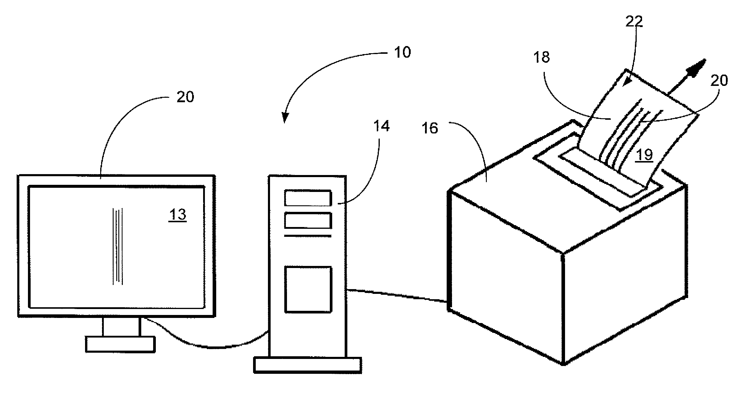
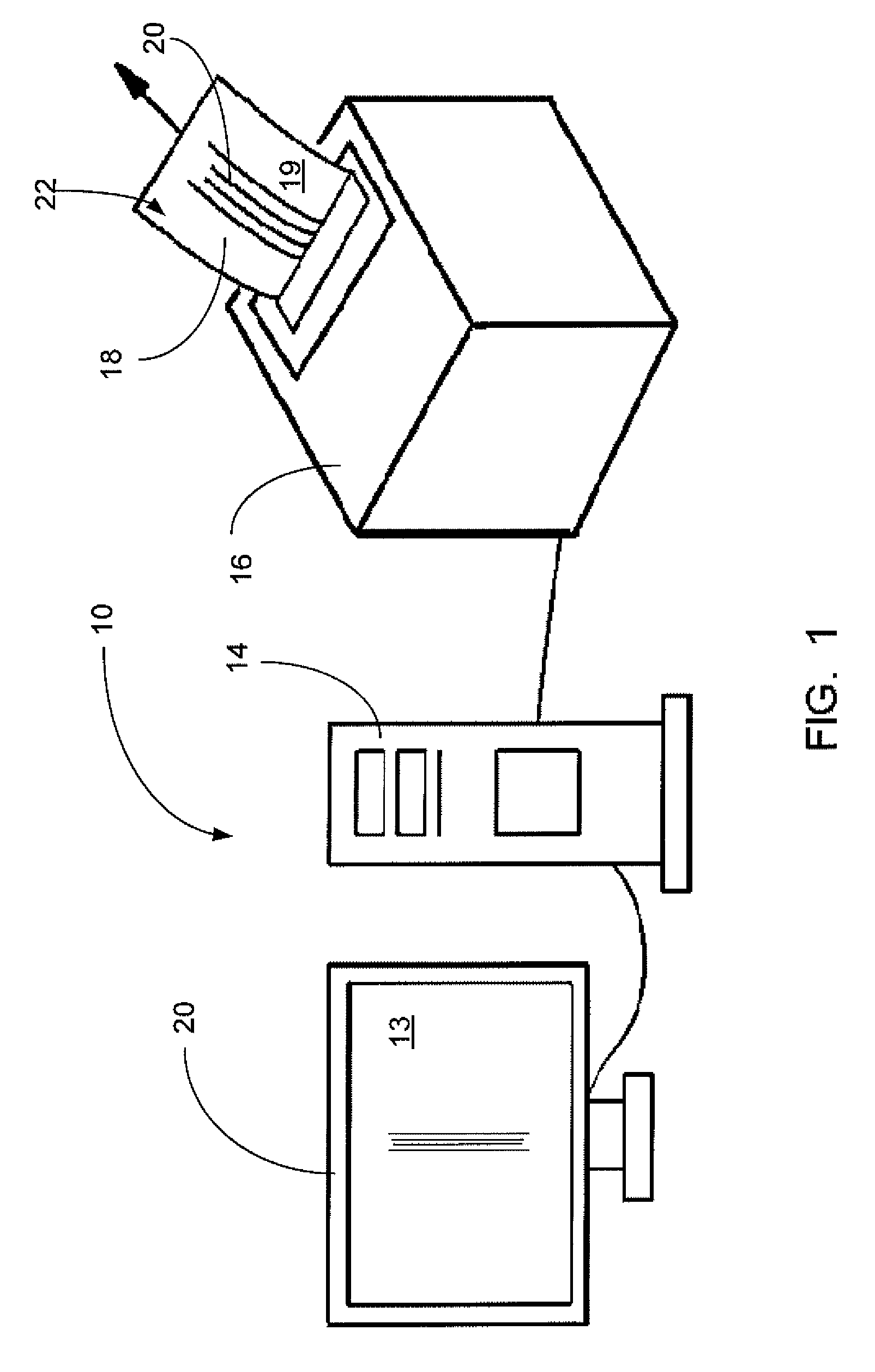
[0061]FIGS. 1-15C illustrate the preferred embodiment of the system of the present invention. However, before a discussion of the process itself, as shown in the Figures, applicant would note the following material. In consideration of the failed attempts to produce a satisfactory ink jet drumstick printer, and the knowledge of the potential benefits which might be realized with a laser printer, a serious attempt was made to develop a laser drumstick printer. One approach which was considered was the application of laser toners directly to the surface of the drumstick. In such a process, the application step would be followed by a fusing stage which would involve some sort of heat process (i.e. heated rollers or oven) to melt the toner powders, thereby fusing them to the surface of the drumstick. The major complication of this approach is the fact that conventional laser printers have been designed to accommodate paper, not drumsticks, and the application of the layers of the indivi...


PUM

PropertyMeasurementUnit
timeaaaaaaaaaa
timeaaaaaaaaaa
cycle timeaaaaaaaaaa

Abstract

The process, which includes the concept of first producing a unique type of heat transfer formed of laser toner particles as well as the subsequent application of the heat transfer to a drumstick or decorated item, would include the steps of obtaining a sheet, roll, belt, etc. of suitable carrier material which has been treated or coated with a release agent (i.e. silicone coated paper); loading carrier material into a laser printer which has had the fusing stage removed or otherwise altered to facilitate the formation of laser toner images on the carrier material; using the laser printer to print a laser toner powder form of the desired image onto the carrier material via computer instruction; obtaining item to be printed and loading it into the heat transfer application machine; loading or feeding heat transfer as described into heat transfer application machine; transferring and fusing laser toner powder image to item to be printed with the heat transfer application machine (which applies heat and pressure in a controlled fashion to the unprinted side of the heat transfer such that the laser toner powders are pressed against the item to be printed); and removing printed item and used carrier material from application machine, with the heat transfer itself exhibiting characteristics which distinguish it as unique and particularly well suited to various applications.

Description

CROSS-REFERENCE TO RELATED APPLICATIONS[0001]Priority of U.S. Provisional Patent Application Ser. No. 60 / 700,874, filed Jul. 20, 2005, incorporated herein by reference, is hereby claimed.STATEMENT REGARDING FEDERALLY SPONSORED RESEARCH OR DEVELOPMENT[0002]Not applicableREFERENCE TO A “MICROFICHE APPENDIX”[0003]Not applicableBACKGROUND OF THE INVENTION[0004]1. Field of the Invention[0005]The subject of the present invention relates to printing on a flat, cylindrical, curved or irregular surface. More particularly, the invention relates to a process to print on the surface of a drumstick (or any other contoured, irregular, or flat surface which lends itself to the process) utilizing a unique type of heat transfer procedure which imparts several beneficial properties to the resultant decorated item.[0006]2. General Background[0007]The concept of covering the surface of a drumstick in whole or in part with various types of decorative and / or functional coatings is discussed in U.S. Pat. ...

Claims


Application Information

Patent Timeline
Patent Type & Authority Patents(United States)
IPC IPC(8): G10D13/02
CPCG03G15/6591G03G15/1625G03G2215/00523
Inventor POKALLUS, KEVIN
Owner POKALLUS KEVIN
Why Eureka
Try Eureka