
Apparatus for abatement of by-products generated from deposition processes and cleaning of deposition chambers

a technology for by-products and equipment, which is applied in the direction of lighting and heating equipment, separation processes, machines/engines, etc., can solve the problems of shortening the life of equipment, high disposal fees for spent bottles, and high system costs, etc., and achieves the effect of ensuring the removal

Inactive Publication Date: 2009-02-24
APPLIED MATERIALS INC
View PDF14 Cites 9 Cited by
  • Summary
  • Abstract
  • Description
  • Claims
  • Application Information

AI Technical Summary

Benefits of technology

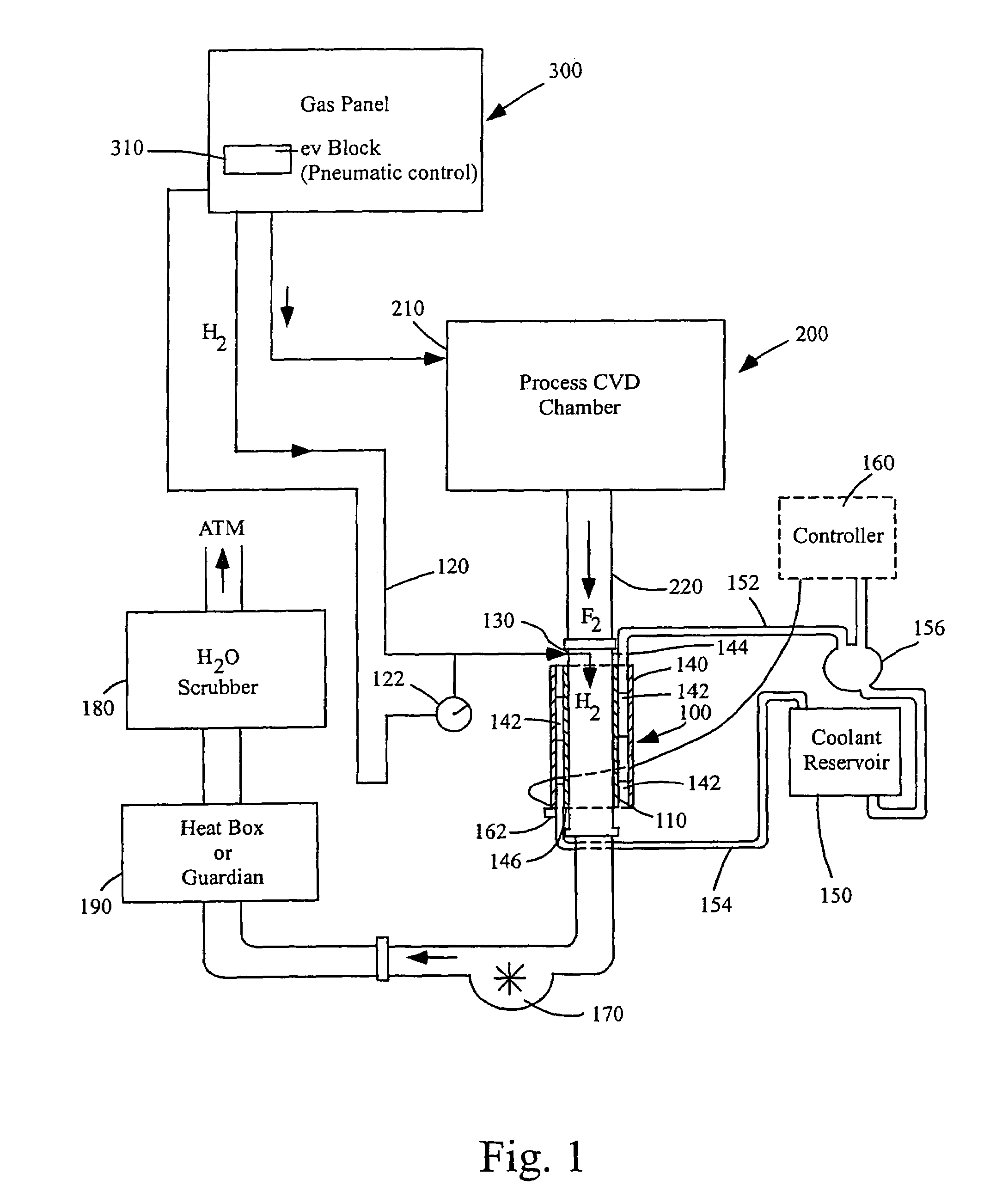
Effectively abates F2 by converting it to HF, reducing the environmental impact and operational costs, while minimizing the system's footprint and extending its lifespan through efficient reaction management.

Problems solved by technology

Left uncleaned, at some point these deposits can crack and fall or flake off, with a possibility of contaminating the substrate that happens to be in the chamber for processing at the time.
Unfortunately, many of these by-products are hazardous air pollutants, which pose a strong environmental concern as they may negatively effect such problems as global warming, ozone deterioration, etc.
Although this system is widely used and has a relatively small footprint, it is susceptible to heavy use of corrosive gases which may significantly shorten its life span, and more than one unit may be needed to adequately abate cleaning by-products from a chamber capable of processing 300 mm wafers.
More importantly, this system does not remove hazardous air pollutants, such as F2 from the exhaust gases.
However, hydrogen is not treated by this tool and therefore an incinerator is still needed for treating hydrogen.
Disposal fees for the spent bottles are also high.
This type of system requires a wastewater stream of about two gallons per minute, the drainage of which can be problematic, and the system itself is also very expensive and requires an additional space on the processing floor, due to its footprint.

Method used


Image

  • Apparatus for abatement of by-products generated from deposition processes and cleaning of deposition chambers
  • Apparatus for abatement of by-products generated from deposition processes and cleaning of deposition chambers
  • Apparatus for abatement of by-products generated from deposition processes and cleaning of deposition chambers

Examples


Embodiment Construction

[0030]Before the present processes are described, it is to be understood that this invention is not limited to particular processes described, as such may, of course, vary. It is also to be understood that the terminology used herein is for the purpose of describing particular embodiments only, and is not intended to be limiting, since the scope of the present invention will be limited only by the appended claims.

[0031]Where a range of values is provided, it is understood that each intervening value, to the tenth of the unit of the lower limit unless the context clearly dictates otherwise, between the upper and lower limits of that range is also specifically disclosed. Each smaller range between any stated value or intervening value in a stated range and any other stated or intervening value in that stated range is encompassed within the invention. The upper and lower limits of these smaller ranges may independently be included or excluded in the range, and each range where either, ...


PUM

PropertyMeasurementUnit
temperatureaaaaaaaaaa
temperaturesaaaaaaaaaa

Abstract

Method and apparatus for abating F2 from by-products generated during cleaning of a processing chamber. F2 abatement is efficiently performed by directly injecting H2 in line with a foreline exiting the processing chamber. A tube which is highly resistant to oxidation and corrosive gases, even at high temperature, is connected in line with the foreline as part of the exhaust line of the processing chamber. A cooling jacket may be provided for cooling the tube, since the reaction between F2 and H2 is exothermic. A pressure monitoring arrangement may also be employed to insure that pressure within a hydrogen line, that feeds the injection of H2 into the tube, does not exceed a predetermined pressure value.

Description

CROSS-REFERENCES TO RELATED APPLICATIONS[0001]This application is a division of U.S. application Ser. No. 09 / 908,668, filed Jul. 18, 2001, which is incorporated herein by reference in its entirety for all purposes.BACKGROUND OF THE INVENTION[0002]The present invention relates to apparatus and processes used for abatement of by-products generated when cleaning depositions left in a chamber used to deposit layers of material in semiconductor manufacturing processes.[0003]During a typical CVD (i.e., chemical vapor deposition) process, deposition gas or gases inside a processing chamber form a thin film layer on the surface of a substrate being processed. Some CVD processes react two or more gases together to form the desired layer. For example, an oxygen source gas may be mixed with a silane source gas to form a type of silicon dioxide layer. Organosilanes also may be used as precursor gases, and are oxidized to form organosilicon oxides. During the deposition of a layer, not only does...

Claims


Application Information

Patent Timeline
Patent Type & Authority Patents(United States)
IPC IPC(8): F01N3/08A62D3/00B01D53/68C01B7/19C23C16/44
CPCB01D53/68C01B7/191C23C16/4405C23C16/4412B01D2251/202B01D2257/2027
Inventor POKHARNA, HIMANSHULE, PHONGNEMANI, SRINIVAS D.
Owner APPLIED MATERIALS INC
Learn More