
Microlensed focal plane array (FPA) using sub-pixel de-selection for improved operability

a focal plane array and micro-lensed technology, applied in the field of micro-lensed fpas, can solve the problems of poor image uniformity, defective or bad detectors are typically much worse than, and the optical collection efficiency of smaller detectors is reduced, so as to improve the collection efficiency, reduce the impact, and be cost-effective.

Active Publication Date: 2009-02-17
TELEDYNE SCI & IMAGING
View PDF7 Cites 1 Cited by
  • Summary
  • Abstract
  • Description
  • Claims
  • Application Information

AI Technical Summary

Benefits of technology

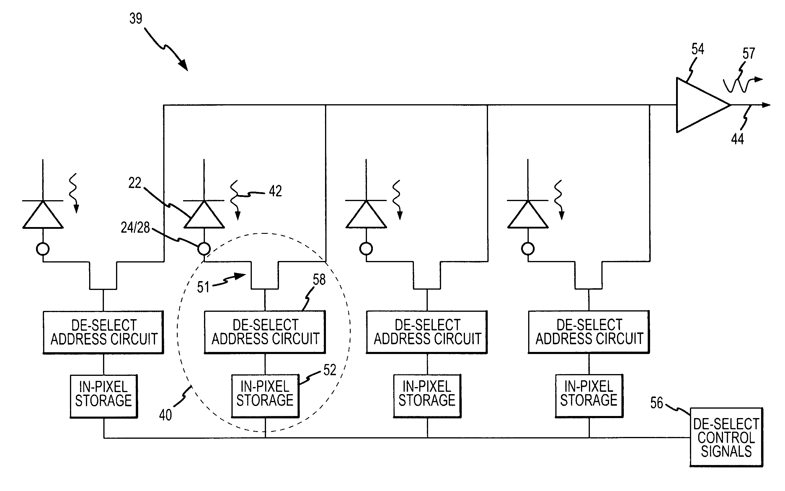
[0009]The present invention provides a cost-effective, robust and flexible FPA having a plurality of sub-pixel detectors per pixel, wherein radiation is directed to all of the sub-pixel detectors in each pixel by a microlens array and any defective detectors are de-selected in the ROIC.
[0010]In a preferred embodiment, the FPA has a microlens array that concentrates radiation into a focal region within each pixel that is covered by the union of the detectors' collection regions. Each detector is connected to a separate and selectable input of a ROIC. The operability of each detector is evaluated, and a map generated specifying detector operability for each pixel. The FPA may be periodically recalibrated and the map updated. This map is read into memory in the ROIC to de-select bad detectors. Detectors are preferably located in close proximity to each other and bad detectors are allowed to float to a photovoltage and re-emit some of their accumulated photo charge to neighboring detectors to improve collection efficiency. The signal created by this collected radiation-induced charge within each pixel is preferably read out on a pixel-by-pixel basis. Accordingly, the signals from the selected detectors are combined within each pixel.
[0011]This approach reduces the impact of both material and fabrication defects, since detectors which are defective for any reason can be screened out. This approach has minimal impact on cost, since the same microlens mask set can be used for each FPA and the ROIC can be configured for de-selection quite easily. Any reduction in optical collection efficiency associated with the de-selection of an illuminated detector is mitigated somewhat by allowing bad detectors to float. The slightly lower performance compared to Lee's approach is in most cases more than offset by the cost and time savings of not requiring a custom microlens mask set for each FPA. Furthermore, the ROIC can be reconfigured in the field during periodic recalibration. Thus, if a sub-pixel detector goes bad it can be de-selected and the pixel remains operable. In addition, because the pixel current represents the sum of multiple detectors, the pixel may be more robust to any degradation in any individual detector.

Problems solved by technology

In such arrays, some detectors will often be inoperable due to randomly located material defects such as structural dislocations and processing defects that cause electrical shorts or unacceptably high tunneling currents, resulting in poor image uniformity.
A defective or bad detector will typically be much worse than this.
However, smaller detectors also have reduced optical collection efficiency.
Still, for many applications including hyperspectral imaging using VLWIR FPAs, even 90-98% operability and also clusters of bad pixels may be deemed unacceptable because either spatial or spectral information in a critical band may be lost.
These applications may demand high operability, generally 99% or greater, which is presently not achieved even with the use of microlens arrays.
However, Lee's approach requires a custom microlens mask set that is determined by the most operative detector selection for each FPA, which is expensive.
In addition, should any of these most operative detectors fail subsequent to microlens application, the pixel will be defective.
Furthermore, once the initial testing is done and the microlens is fabricated, it is not possible to recalibrate the FPA to change the selected detector in each pixel.

Method used


Image

  • Microlensed focal plane array (FPA) using sub-pixel de-selection for improved operability
  • Microlensed focal plane array (FPA) using sub-pixel de-selection for improved operability
  • Microlensed focal plane array (FPA) using sub-pixel de-selection for improved operability

Examples


Embodiment Construction

[0017]The present invention provides an FPA having a plurality of sub-pixel detectors per pixel, wherein radiation is directed to all of the detectors in each pixel by a microlens array and any defective detectors are de-selected in the ROIC. An FPA comprises three essential components: a microlens array, a detector array and a ROIC. The present invention modifies the detector array and ROIC to provide for de-selection of bad sub-pixel detectors in each pixel at manufacturer and, possibly, during periodic recalibration to improve operability. The present invention uses conventional microlens designs that are independent of the de-selection of particular sub-pixel detectors. This allows for the use of a single standard microlens mask set for each FPA to keep costs down.

[0018]There are many types of FPAs for detecting electromagnetic radiation of varying wavelengths. This invention is applicable to virtually any type of FPA, and is most useful for very long wavelength Infrared (VLWIR)...


PUM


Abstract

A cost-effective FPA includes a plurality of detectors per pixel, wherein radiation is directed by a microlens array into respective focal regions that are covered by the union of the detectors' collections regions within each pixel and any defective detectors are de-selected in the ROIC. The operability of each pixel is evaluated, and a map generated specifying detector de-selection for each pixel. This map is read into memory in the ROIC to de-select bad detectors. Bad detectors are preferably allowed to float to a photovoltage and re-emit some of their accumulated photo charge to neighboring detectors to improve collection efficiency. The radiation levels are preferably read out on a pixel-by-pixel basis. Accordingly, the signals from the selected detectors are combined within each pixel.

Description

BACKGROUND OF THE INVENTION[0001]1. Field of the Invention[0002]This invention relates to microlensed FPAs and more specifically to a method of configuring the detector array and ROIC for sub-pixel de-selection to improve operability.[0003]1. Description of the Related Art[0004]A photodetector registers photon flux striking it as a function of time. An array of a large number of photodetectors can simultaneously register the photon fluxes from many spatial points (called pixels) to form an electronic version of an optical image. In such arrays, some detectors will often be inoperable due to randomly located material defects such as structural dislocations and processing defects that cause electrical shorts or unacceptably high tunneling currents, resulting in poor image uniformity. A detector is typically considered operable if its sensitivity (signal-to-noise ratio, or some other parameter such as quantum efficiency, noise, or dark current or a combination of these parameters) is w...

Claims


Application Information

Patent Timeline
Patent Type & Authority Patents(United States)
IPC IPC(8): H01L27/00H04N9/64
CPCG01J1/04G01J1/0411G01J1/4228H01L27/14625H01L27/14627G01J1/0204H04N5/367H04N25/68
Inventor LEE, DONALD L.TENNANT, WILLIAM E.
Owner TELEDYNE SCI & IMAGING
Learn More