
Solar Panel Tracking and Mounting System

a solar panel and mounting system technology, applied in photovoltaic supports, sustainable buildings, light and heating equipment, etc., can solve the problems of complex and cost, maximizing solar energy collection, and generating complexity in solar systems, so as to improve solar energy collection efficiency, reduce the angle of incidence, and increase the effect of energy saving

Inactive Publication Date: 2010-12-09
GRAVITAS GROUP
View PDF4 Cites 51 Cited by
  • Summary
  • Abstract
  • Description
  • Claims
  • Application Information

AI Technical Summary

Benefits of technology

[0009]Every solar system is propelled by the suns rays, one by-product of which is an abundance of stored energy that can be utilized directly. Most such systems employ solar panels and tilting means to minimize angle of incidence (AOI) thereby increasing energy savings.
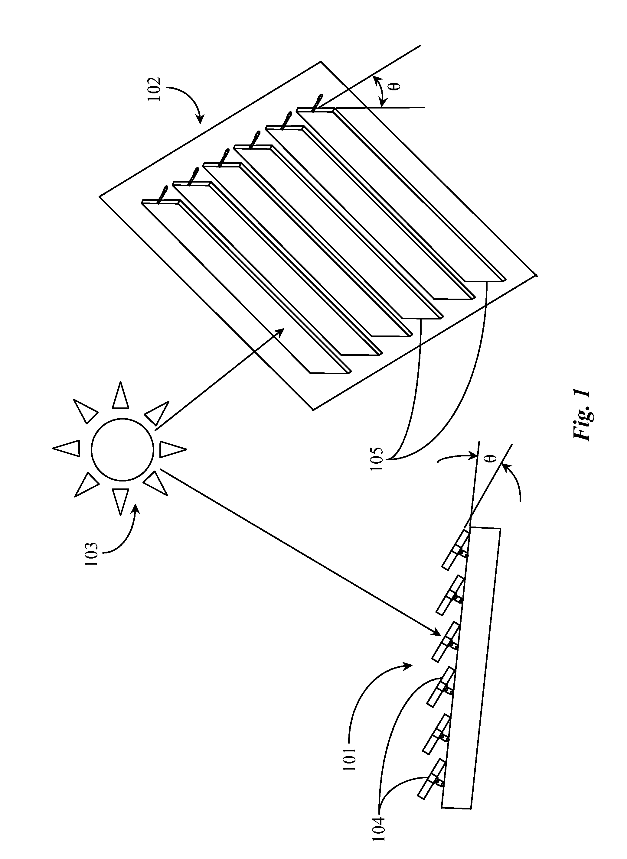
[0010]The present inventor realized in an inventive moment that if, during solar tracking, modular solar collecting devices could be caused to track the sun in unison using both synchronous and counter synchronous tracking such that by one or more pivot axis' the panels may be caused to tilt and / or track along those axis', more solar efficiency in solar energy collection might be realized. The inventor therefore constructed a unique modular system of solar collection devices for rooftops and commercial installations that allowed minimization of AOI during solar tracking thereby increasing solar collection efficiency during the solar tracking operation. A significant reduction in work results, with no impediment to solar footprint or existing solar efficiency ratings created.

Problems solved by technology

The problem stated above is that maximum efficiency is desirable for a solar collector system or array, but many of the conventional means for maximizing solar energy collection is solar system also create complexity and cost.

Method used


Image

  • Solar Panel Tracking and Mounting System
  • Solar Panel Tracking and Mounting System
  • Solar Panel Tracking and Mounting System

Examples


Embodiment Construction

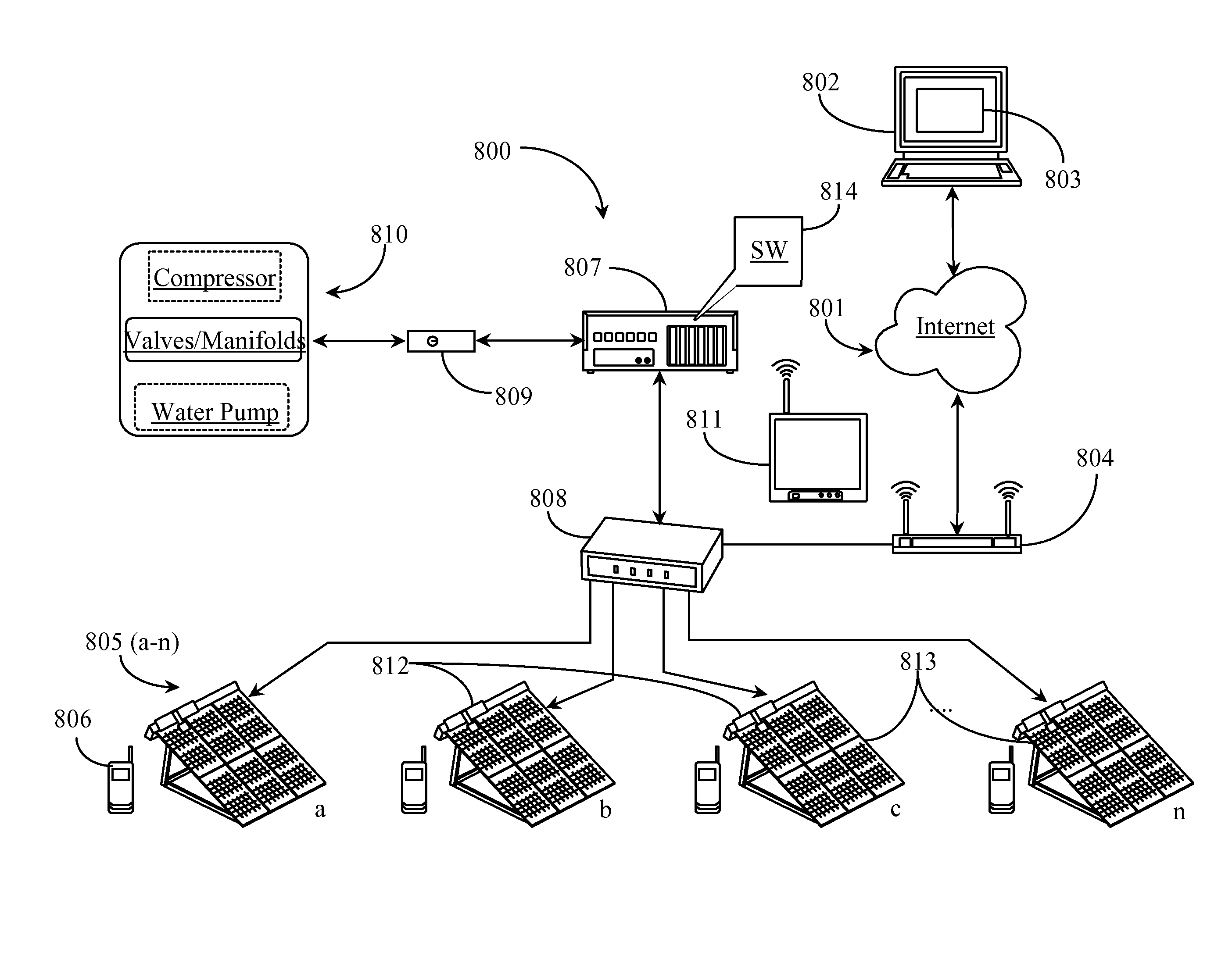
[0045]The inventor provides a modular solar collector system that has dual sun-tracking capabilities, self-inspection and self-cleaning maintenance capabilities, and other general improvements over standard art systems for residential and commercial use. The present invention is described in enabling detail using the following examples, of which may show more than one useful embodiment of the present invention.

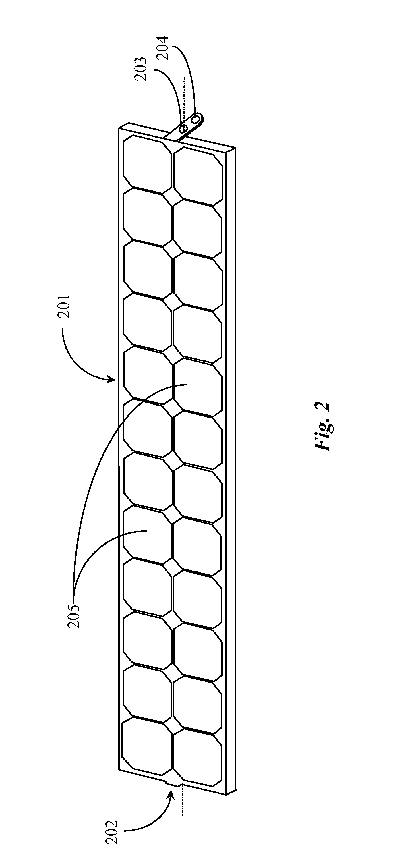
[0046]The terms solar panel and solar module are commonly used interchangeably in documents that describe conventional solar collecting systems. However, in this specification, and to avoid confusion, the terms modular solar collecting device or simply modular device shall be used to reference a fully-functioning solar collecting unit enclosed in a rigid sub-structure with full electrical and / or thermal connections. The modular device of the present invention two or more such devices comprising a modular solar collecting system, may be functionally similar to solar panels / modu...


PUM


Abstract

A method for tracking solar panels includes the steps (a) beginning a tracking cycle substantially at sunrise with adjacent tilting panels all horizontal, (b) tilting the adjacent panels in unison in a first angular direction toward the rising sun at a tilt rate that just avoids shading of adjacent panels, (c) reversing direction of panel tilt at a point that the panels reach either a maximum tilt limited by mechanical design, or the panel surfaces are orthogonal to the rising sun, (d) tilting the adjacent panels in a second angular direction, following movement of the sun and keeping the surface of the panels at right angles to the sun's position, until a point is reached that shadowing is imminent from the angle of the setting sun, and (e) reversing direction of panel tilt again to the first angular direction, adjusting tilt as the sun sets to avoid shading until the panels are again horizontal.

Description

CROSS-REFERENCE TO RELATED APPLICATIONS[0001]The present invention claims priority to a U.S. provisional patent application Ser. Nos. 61 / 217,794, filed on Jun. 3, 2009, 61 / 268,237, filed on Jun. 9, 2009, and 61 / 311,745, filed on Mar. 8, 2010, disclosures of which are incorporated at least by reference.BACKGROUND OF THE INVENTION[0002]1. Field of the Invention[0003]The present invention is in the field of solar tracking systems and pertains particularly to methods and apparatus for tracking the sun using at least one tilt angle while minimizing any shadowing on adjacent solar collection panels.[0004]2. Discussion of the State of the Art[0005]In the field of solar tracking systems, there are system that can produce substantially more energy (watts / panel) compared to fixed arrays of the same type and capacity by enabling tracking of the sun. This difference is most pronounced for those using crystalline silicon PV technologies, where a single-axis tracking systems could add up to 30% m...

Claims


Application Information

Patent Timeline
IPC IPC(8): F24J2/38F24J2/00F24S50/20
CPCY02E10/50F24J2/38F24J2/40Y02B10/12H01L31/052Y02E10/47H02S20/00F24J2/541H02S20/32F24S50/20F24S30/425F24S50/00
Inventor PARK, KEN HYUN
Owner GRAVITAS GROUP
Learn More