
Integrated cogeneration wastewater sewage and waste polar fats/ oils/ greases/waxes (FOG) waste treatment method and facility

a cogeneration wastewater and treatment method technology, applied in the field of integrated digestible wastes (sewage and otherwise), and waste polar fats/oils/greases/waxes (fog) treatment methods, systems and facilities, can solve the problems of large percentage of sewer system failures and overflows, and failure of the functional components of the sewer system

Inactive Publication Date: 2009-02-03
MAGNER JOSEPH A +1
View PDF18 Cites 11 Cited by
  • Summary
  • Abstract
  • Description
  • Claims
  • Application Information

AI Technical Summary

Benefits of technology

The system achieves a positive net energy gain through increased steady-state methane production and significantly reduces solids volume, enabling efficient electricity generation and thermal energy use while avoiding clogs and disposal issues.

Problems solved by technology

Excessive concentrations of FOG (fats, oils, waxes and greases) are a major problem in wastewater / sewage collection and treatment systems.
Because of the prevalence of food service and processing enterprises in populated environs, polar FOG is responsible for a large percentage of sewer system failures and overflows.
In particular, polar FOG, if not intercepted congeals on and sticks to piping and fixtures in wastewater systems, and, as well, to other debris flowing in the waste stream creating plugs and causing functional failures of the sewer system components.
This type of FOG is typically detrimental to wastewater treatment systems / processes and, in particular, to the biologic phase of waste treatment process inhibiting (poisoning) microorganisms that breakdown or digest the wastes.
However, grease traps and interceptors have limited capacities.
Or more seriously, as the traps / interceptors approach capacity, input wastewater tends to entrain both FOG and other materials as it streams through the FOG / solids filled trap / interceptor tank inducing failures downstream in the sewer system.
The so tanked ‘BROWN’ FOG evacuate from grease traps / interceptors is an unholy, difficult to handle, smelly, watery, sticky mess.
Properly disposing of such tanked ‘BROWN’ FOG evacuate is a problem precisely because it is contaminated, contains rocks, glass, tableware, both broken and not, bones and other items people thoughtlessly, or purposely toss / flush down drains at public and commercial establishments.
Historically, such ‘BROWN’ FOG evacuate has been deemed ‘toxic’ and is required to be disposed of in landfills appropriately isolated from aquifers and surface drainages.
Existing appropriate disposal sites are filling up, and new sites are difficult to find, and once found, economically expensive to establish and maintain.
Finally, after a landfill site reaches capacity, its possible uses are limited far into the foreseeable future.
Problems experienced at the SBSA facility primarily relate to handling of the ‘BROWN’ FOG evacuate, and to spiking of biogas production with each cleaned ‘BROWN’ FOG evacuate loaded into the digester.
Again, the problems experienced at the OWD treatment plant, akin to those at SBSA, relate to material handling (clogs) and spiking biogas production when the ‘BROWN’ FOG evacuate is offloaded to the digester.

Method used


Image

  • Integrated cogeneration wastewater sewage and waste polar fats/ oils/ greases/waxes (FOG) waste treatment method and facility
  • Integrated cogeneration wastewater sewage and waste polar fats/ oils/ greases/waxes (FOG) waste treatment method and facility
  • Integrated cogeneration wastewater sewage and waste polar fats/ oils/ greases/waxes (FOG) waste treatment method and facility

Examples


Embodiment Construction

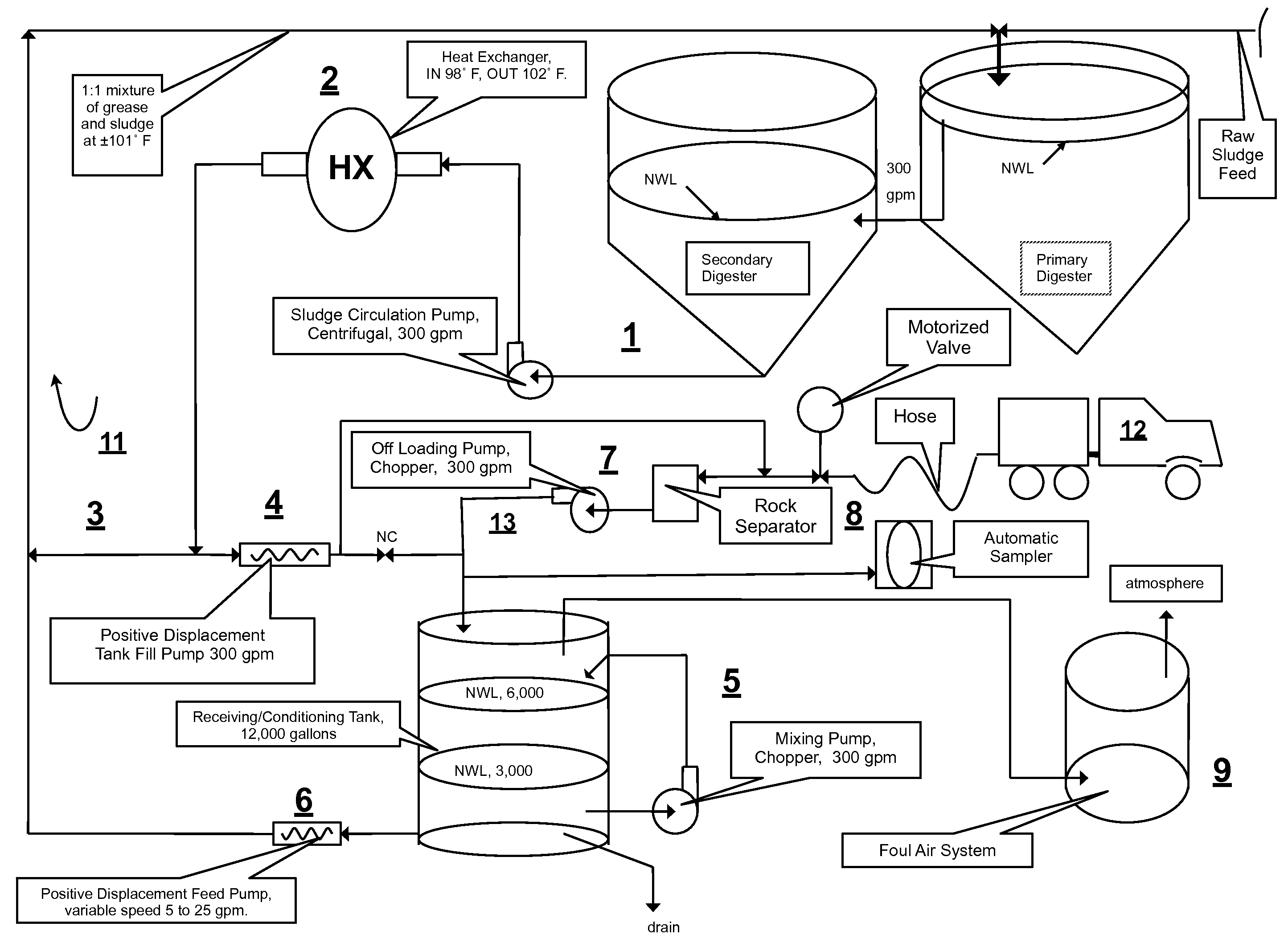
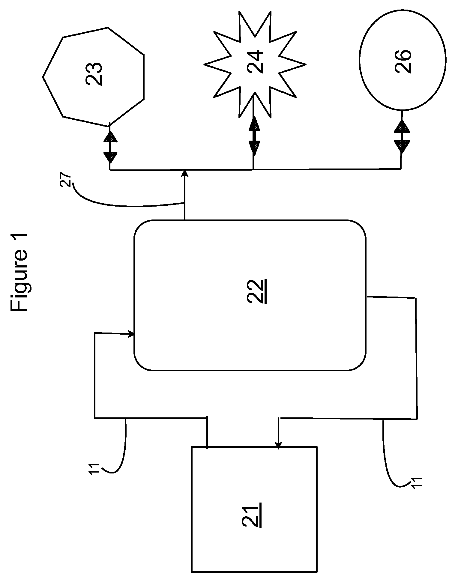
[0021]Looking at FIG. 1 the invented integrated cogeneration system for treating raw sewage, and polar fats / oils / greases / waxes (FOG) wastes includes a FOG receiving and pre-treatment station 21 receiving actively digesting sludge circulating in a slipstream loop 11 from the base or bottom of a digestible wastes treatment facility 22, and outputting a highly bioreactive, flowable, feedstock slurry mixed with actively digesting sludge circulating in the slipstream loop 11 to the top or head / input end of the wastes treatment facility 22. Produced methane gas is either used to generated electrical power 23, combusted to produce thermal energy 24, or stored 26 for future use.

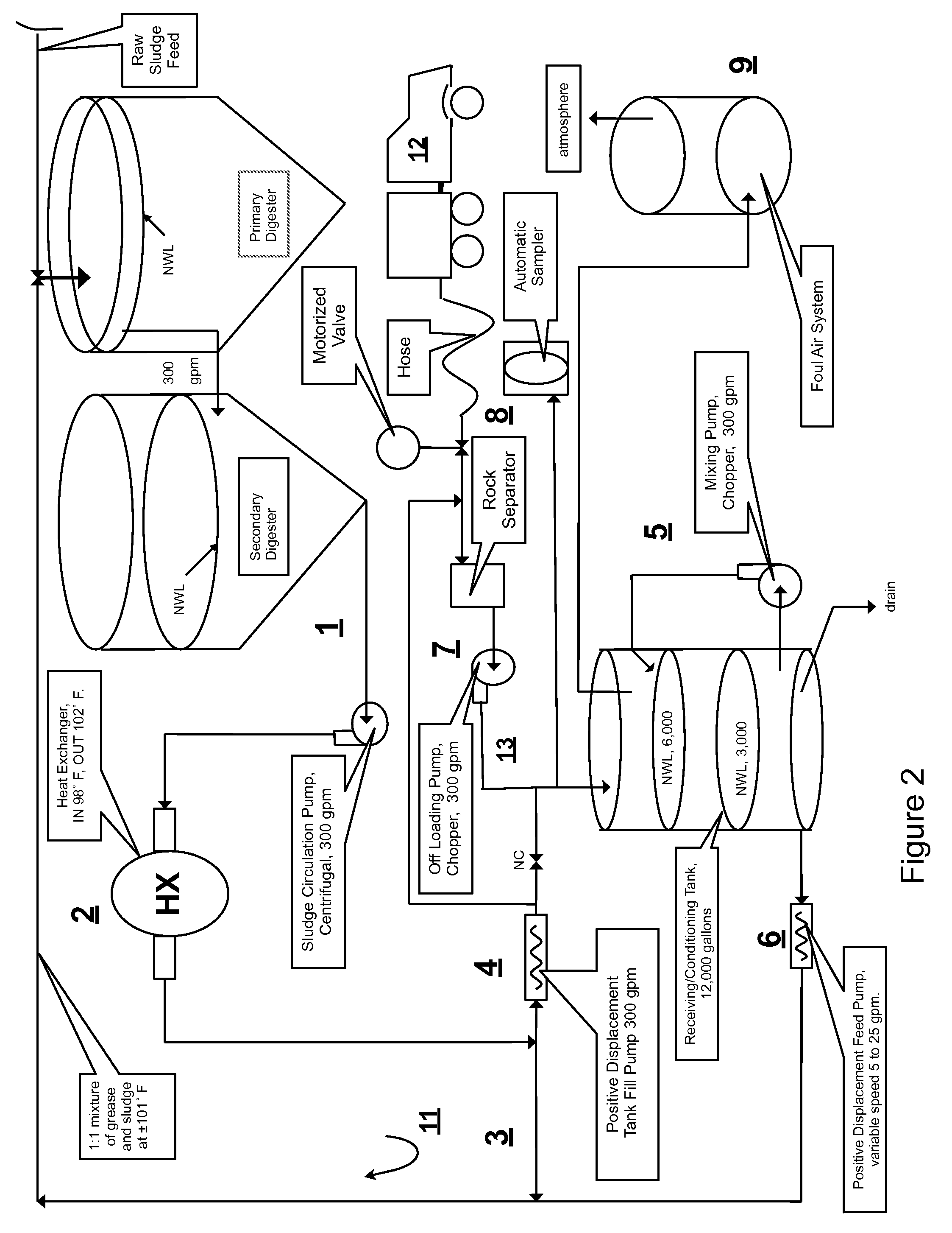
[0022]The wastes treatment facility 22 is located in Millbrae, Calif. and is an Acid / Gas Mesophilic acid phase—Mesophilic gas phase (AGMM) system where a primary anaerobic digester receives raw sewage, and pours over to a secondary anaerobic digester. The overall objective of the integration was to increase steady-st...


PUM

PropertyMeasurementUnit
temperaturesaaaaaaaaaa
temperatureaaaaaaaaaa
volumeaaaaaaaaaa

Abstract

A system and method integrating treatment of waste, polar Fats / Oils / Greases (FOG) with conventional anaerobic wastewater treatment facilities for biologically fueling digestion of solids in, and steady state production of methane from treated wastewater streams that includes a slipstream loop circulating warmed, actively digesting sludge from the base to the head of the anaerobic wastewater treatment facility, a conditioning tank with input screened by a rock trap, actively digesting sludge pumped from the slipstream loop into the tank via the rock trap, before and after FOG wastes are pumped from a hauler tank via a hose connecting to the rock trap into the conditioning tank and mixed with actively digesting sludge in the tank to produce a feedstock slurry rich in volatile fatty acids for injection at a metered rate back into the actively digesting sludge slipstream loop for introduction at the head of the anaerobic wastewater treatment facility.

Description

RELATED APPLICATIONS[0001]This Application claims all benefits applicable under 35 U.S.C. §119(e) related to U.S. Provisional Patent Application Ser. No. 60 / 892,068 filed on behalf of the Applicants on Feb. 28, 2007 also entitled “INTEGRATED COGENERATION WASTEWATER SEWAGE AND WASTE POLAR FATS / OILS / GREASES / WAXES (FOG) WASTE TREATMENT METHOD AND FACILITY”, which is incorporated herein by reference in its entirety.BACKGROUND OF THE INVENTION[0002]1. Field of the Invention[0003]The invention relates to integrated digestible wastes (sewage and otherwise) and waste polar fats / oils / greases / waxes (FOG) treatment methods, systems and facilities including anaerobic digesters and steady-state generation of methane.[0004]2. Description of the Prior Art[0005]Excessive concentrations of FOG (fats, oils, waxes and greases) are a major problem in wastewater / sewage collection and treatment systems. There are two types of FOG. The first type, polar FOG originates from animals or vegetable (foods). Be...

Claims


Application Information

Patent Timeline
Patent Type & Authority Patents(United States)
IPC IPC(8): C02F3/28C02F11/04
CPCC02F3/286C02F11/04C02F1/025C02F2101/32C02F2101/325C02F2103/22C02F2103/26C02F2103/32C02F2103/365C02F2201/009C02F2301/046C02F2303/24Y02E50/343C12M21/04C12M23/58C12M43/08C12M47/18Y02A20/212Y02E50/30Y02W10/10Y02W10/20Y10S210/916
Inventor MAGNER, JOSEPH A.YORK, RICHARD V.
Owner MAGNER JOSEPH A
Learn More