Light emitting device
a technology of light emitting device and light source, which is applied in the direction of semiconductor devices, basic electric elements, electrical apparatus, etc., can solve the problems of increasing manufacturing cost, complicated structure, and complicated structure of gan-based led, and achieves simple structure, high emission efficiency, and easy manufacturing
- Summary
- Abstract
- Description
- Claims
- Application Information
AI Technical Summary
Benefits of technology
Problems solved by technology
Method used
Image
Examples
embodiment 1
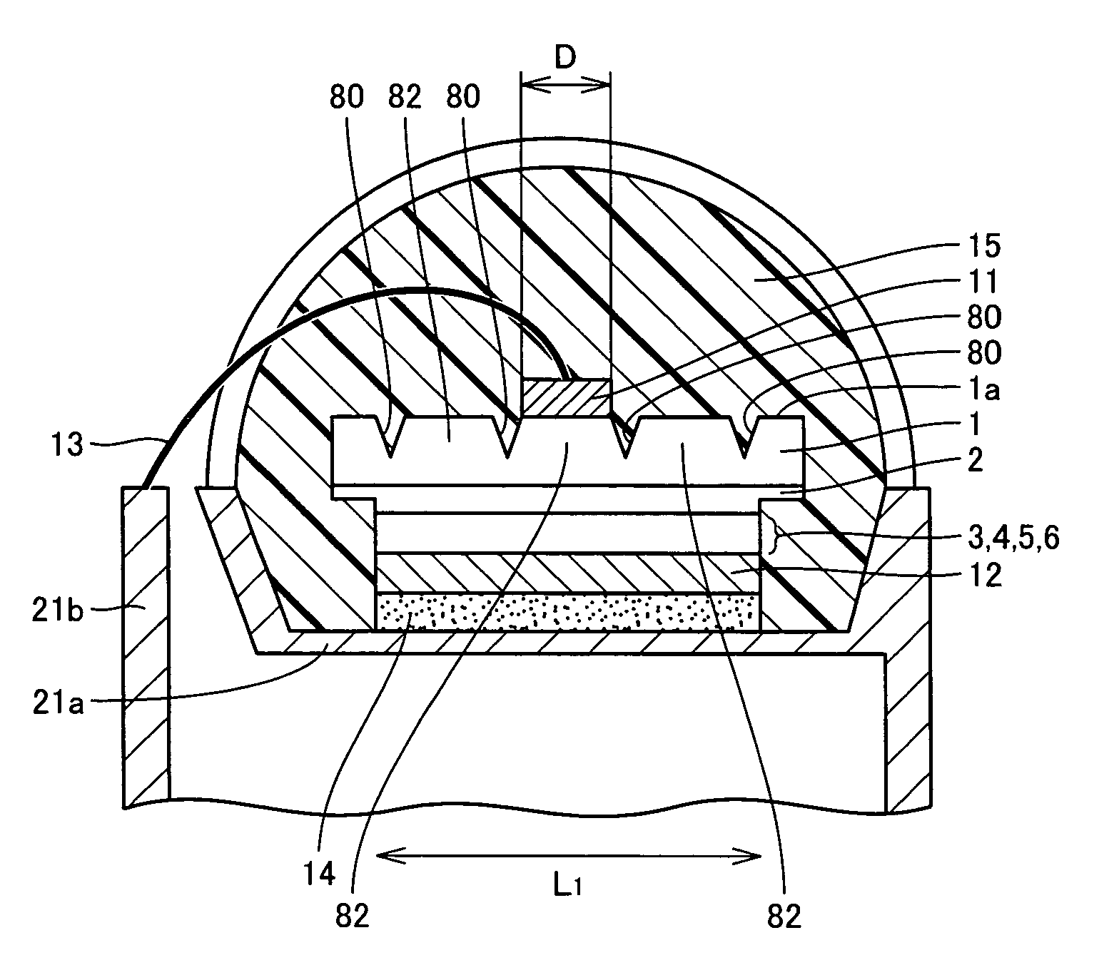
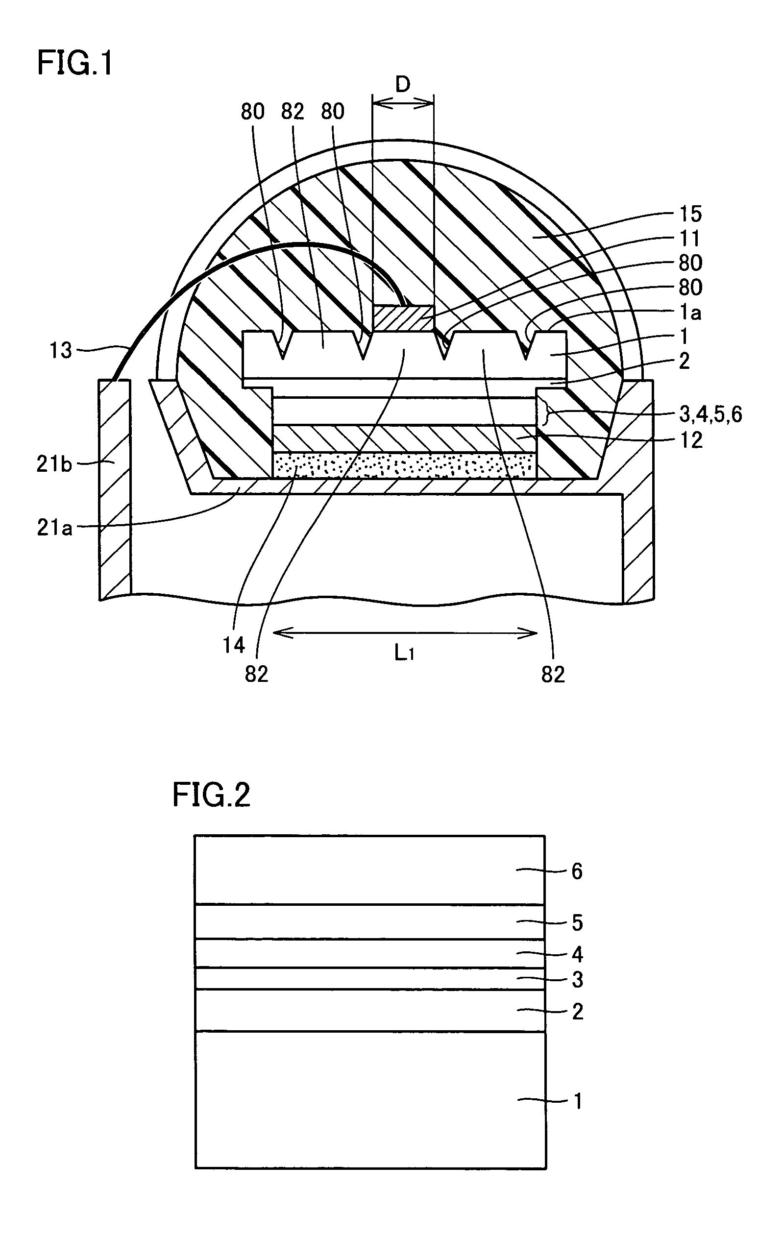
[0118]First, a sapphire substrate and the GaN substrate as the nitride semiconductor substrate will be compared. Here, an LED as Example A of Embodiment 1 of the present invention has the same structure as the LED shown in FIG. 1. In the following, the LED of Example A will be described with reference to FIG. 1. As shown in FIG. 1, the LED of Example A has a stacked structure, which will be described in detail later, including a light generating layer and the like formed on the side of the first main surface of GaN substrate 1, and p-electrode 12 is provided. One characteristic of the present invention is that p-electrode 12 is mounted face-down on lead frame mounting portion 21a by conductive adhesive 14.
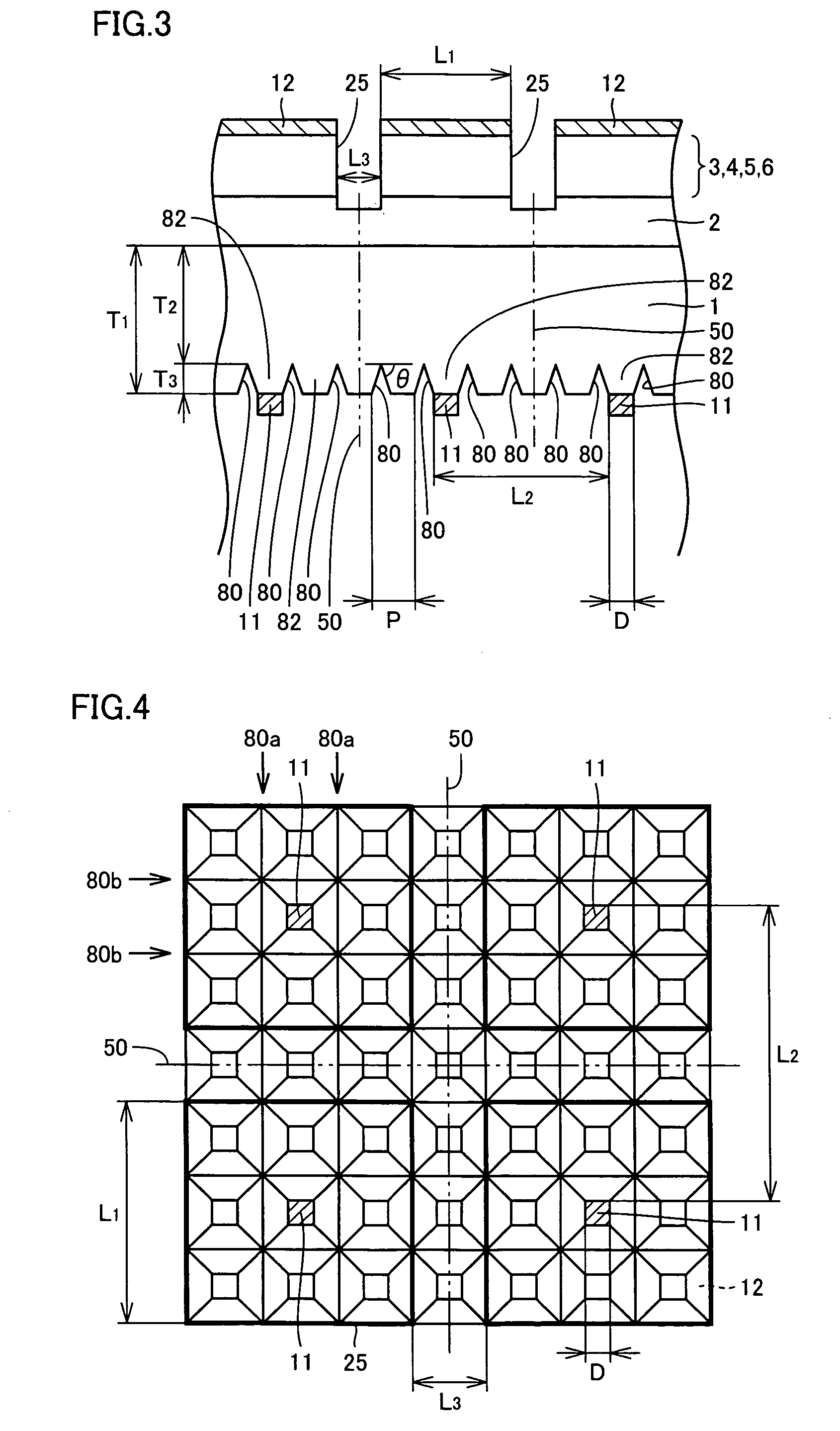
[0119]The second main surface 1a of GaN substrate 1 is a light emitting surface that emits light generated in the light generating layer, and an n-electrode 11 is formed on this surface. A plurality of trenches 80 extending in directions vertical to and parallel to the surface of t...
embodiment 2
[0153]In Embodiment 2, Example C of the present invention having a larger area will be described. Example C of the present invention has the same structure as Example A shown in FIG. 1, except that the length L1, which is 0.3 mm (300 μm) in Example A, is made 3 mm in Example C, that is, ten times larger than Example A. Accordingly, the area is 100 times larger. The method of manufacturing Example C is as follows.
example c
[0154](c1) to (c5) Process steps corresponding to those of Example A of the present invention are performed, except that a large GaN substrate is used.
[0155](c6) On the second main surface as the back surface of GaN substrate, n-electrodes having a square two-dimensional shape, with the width D of each side being 100 μm, were formed each at the center of the chip, apart by 3.1 mm, by photolithography, vapor deposition and lift-off method. As the n-electrode, a stacked structure including (Ti layer of 20 nm / Al layer of 100 nm / Ti layer of 20 nm / Au layer Of 200 nm) in this order from the lower side was formed in contact with the back surface of the GaN substrate. The resulting body then was heated in an inert atmosphere, so that contact resistance was made to be at most 1E-5 Ω·cm 2.
[0156](c7) and (c8) Process steps corresponding to those of Example A of the present invention were performed.
[0157](c9) Thereafter, scribing was performed to attain a prescribed shape, and the resulting chi...
PUM
 Abstract
Description
Claims
Application Information
 - R&D
- Intellectual Property
- Life Sciences
- Materials
- Tech Scout
- Unparalleled Data Quality
- Higher Quality Content
- 60% Fewer Hallucinations
Browse by: Latest US Patents, China's latest patents, Technical Efficacy Thesaurus, Application Domain, Technology Topic, Popular Technical Reports.
© 2025 PatSnap. All rights reserved.Legal|Privacy policy|Modern Slavery Act Transparency Statement|Sitemap|About US| Contact US: help@patsnap.com


