
Heat sealer for stretch wrapping apparatus

a technology of heat sealing and stretch wrapping, which is applied in the field of stretch wrapping, can solve the problems of loose or torn wrap, the load is not protected, and the wrapping of the load is not suitable for use,

Active Publication Date: 2008-12-30
LANTECH COM
View PDF22 Cites 14 Cited by
  • Summary
  • Abstract
  • Description
  • Claims
  • Application Information

AI Technical Summary

Benefits of technology

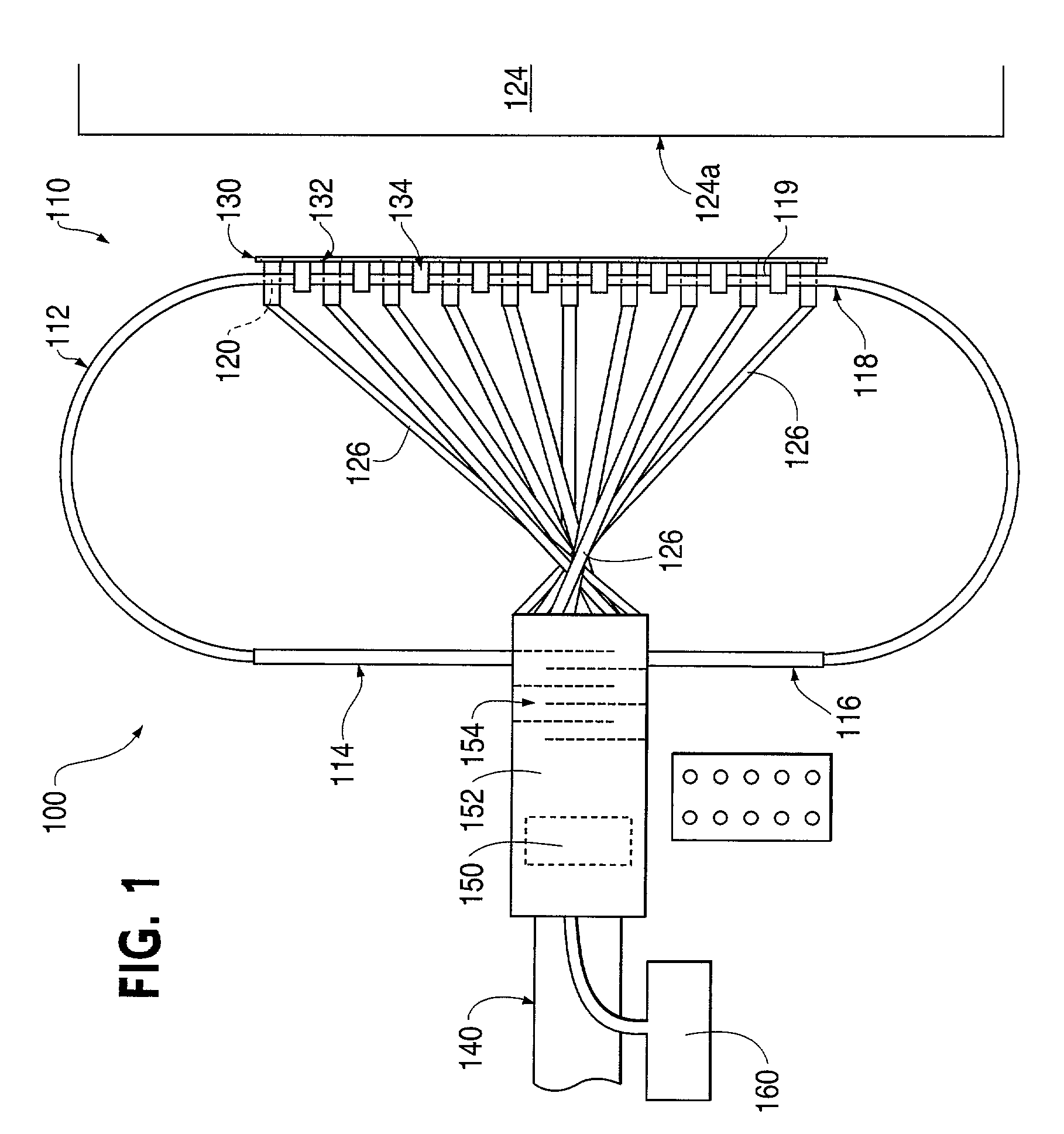
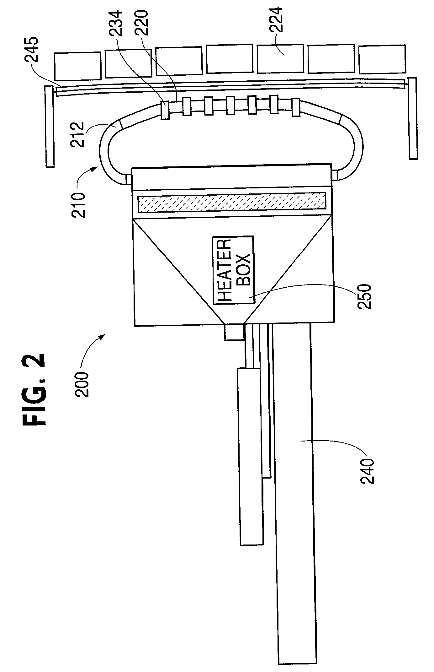
The present invention provides a method and apparatus for wrapping a load with plastic film that overcomes several problems associated with previous methods and devices. The heat sealing device includes a heater element and a sealing head with convection ports and an insulated film contact portion that provides a set distance between the convection ports and the plastic film when in contact with it. The method involves placing the load on a load wrapping surface, providing relative rotation between the load and a plastic film dispenser to wrap the plastic film around the load, pressing a portion of the top layer of the plastic film into a layer of plastic film below it with the sealing head, and applying a stream of heated air to the portion of the top layer of the plastic film from the convection ports to seal it to the layer of plastic film below it while maintaining the convection ports a set distance from the portion of top layer of plastic film. The apparatus includes a dispenser for plastic film, a heat sealing device with convection ports and an insulated film contact portion providing a set distance between the convection ports and the plastic film, and means for providing relative rotation between the load and the plastic film. The technical effects of the invention include improved sealing efficiency, reduced labor costs, and improved load protection.

Problems solved by technology

Most stretch wrap packaging films are manufactured with an element of tackiness to add to their layered stability and to provide a mechanism for closure of the ending film tail, however, wiping is not sufficient to ensure that the tail of the film will not come loose during shipping, resulting in loose or torn wrap.
In addition, in certain circumstances, such as outside storage of loads, open truck transit where winds can cause unwinding of film, or where tacky film is undesirable or unavailable, merely wrapping the load will not protect it.
Sealing plastic wrapping material with heat, however, poses another set of problems.
Radiant sealing is very rare for clear packaging films due to its relative resistance to absorbing radiant energy and the potential fire hazard of proximity to the high temperature elements required.
In the environment where stretch wrappers operate, heat sealing has been very problematic.
Such materials include bulk beverage containers, corrugated containers, construction materials including brick, stone, and concrete, metal and plastic automotive parts, stacks of paper, and most difficult, irregular loads with substantial voids of product behind the film.
As a result of these “backings”, the pressure of the heat sealer often “burns through” the stretch wrap packaging material, resulting in a hole with the potential for product damage from water or other contaminants.
Loads often do not provide a vertically plumb side for the sealing element to contact, thereby preventing one or more of the sealing elements from actually contacting the film.
The somewhat delicate heating element itself may take a beating by repeated contact with the above mentioned loads.
Although a convective sealing apparatus for stretch wrapping is shown in U.S. Pat. No. 4,993,209 to Haloila, the device has not experienced commercial success, most likely due to the types of problems discussed above.

Method used


Image

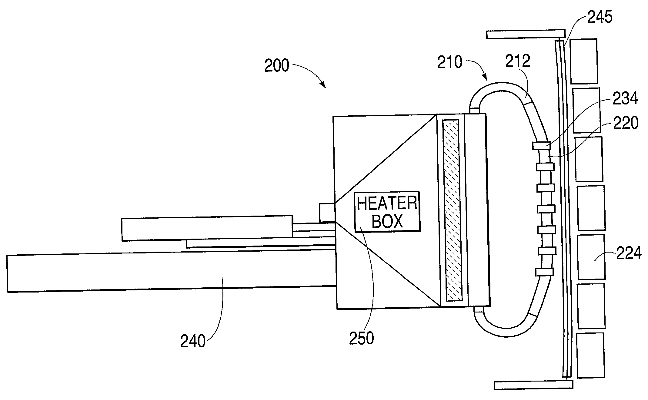
  • Heat sealer for stretch wrapping apparatus
  • Heat sealer for stretch wrapping apparatus
  • Heat sealer for stretch wrapping apparatus

Examples


first embodiment

[0070]Alternatively, as shown in FIG. 6B, standoff insulation element 534b may be positioned above and movable with the heat sealing element (rigid tube 512). As embodied herein, standoff insulation element 534b may form a frame or mask in which rigid tube 512 will apply heat to the plastic packaging material. In this embodiment, the standoff insulation element 534b is not necessarily positioned between the orifices 520 of the rigid tube 512, but instead may form a perimeter around the orifices 520 (FIGS. 13A, 13B). Alternatively, standoff insulation element 534b may comprise a plurality of “bars” forming standoff portions between the orifices 520 or may comprise “bars” only at the ends of the rigid tube 512 (FIGS. 13E and 13F). Any configuration that is sufficient to maintain “cool” portions to contact and compress the layers of plastic packaging material together for heat sealing, while keeping the orifices 520 free of packaging material, is acceptable. These alternate configurati...

second embodiment

[0088]A method for wrapping a load according to the present invention will now be described. In the operation of the inventive wrapping apparatus, full web, spiral web, and banding modes of operation are substantially identical manner. In these modes, a feed conveyor 703 brings the load 724 onto the top load supporting and conveying surface 782 of wrapping conveyor assembly 707. Load supporting and conveying surface 782 then carries the load to a predetermined wrap position within the packaging material dispensing path and the conveyor assembly stops leaving the load in a stationary position.

[0089]A leading edge 777 of the packaging material 778 is held in a clamping assembly 761 located beneath the conveyor assembly 707 as seen in FIGS. 10 and 11. After at least one wrap has been made around the load 724 and the clamp assembly 761, the clamps 761a, 761b are rotated releasing edge 777 which is held by the web wrap. If the wrap is for a full web load or a banded load, a plurality of ...


PUM

PropertyMeasurementUnit
diameteraaaaaaaaaa
relative rotationaaaaaaaaaa
distancesaaaaaaaaaa

Abstract

A heat sealing device for sealing layers of plastic film together is provided. In a preferred embodiment, the heat sealing device is incorporated into a stretch wrapping apparatus for wrapping a load. The heat sealing device includes a heater element, an air compressor or blower, and a sealing head in fluid communication with the heater element to distribute the heated air. The sealing head is preferably flexible and includes a plurality of convection ports configured to apply heated air to a portion of the packaging material without being completely covered by the packaging material. At least one insulated film contact portion is provided to distance the convection ports from the plastic film.

Description

[0001]This application claims priority under 35 U.S.C. § 119 based on U.S. Provisional Application No. 60 / 292,521, filed May 23, 2001, the complete disclosure of which is incorporated herein by reference.DESCRIPTION OF THE INVENTION[0002]1. Field of the Invention[0003]The invention relates to wrapping a load with packaging material, and, more particularly, to stretch wrapping.[0004]2. Background of the Invention[0005]Stretch wrapping can be performed as an inline automated packaging technique which dispenses and wraps packaging material in a stretched condition around a load on a pallet to cover and contain the load. Pallet stretch wrapping, whether accomplished by turntable, overhead arm, or rotating ring typically covers the four vertical sides of the load with a stretchable film such as polyethylene film. After the sides of the load are covered, the web of film is cut and the tail is usually “wiped” to press it against the load. Most stretch wrap packaging films are manufactured ...

Claims


Application Information

Patent Timeline
Patent Type & Authority Patents(United States)
IPC IPC(8): B65B53/02B65B13/02B29C65/00B29C65/10B65B11/02
CPCB29C65/10B29C66/80B29C66/81451B65B11/025B29K2023/0633B29K2023/083B29C66/8322B29C66/73921B29C66/43B29C66/71B29C66/1122B29K2027/06B29K2023/12B29K2023/0691B29K2023/065
Inventor LANCASTER, III, PATRICK R.ELDRIDGE, DAVIDHACK, STEVEN
Owner LANTECH COM
Learn More