
Separator passage structure of fuel cell

a fuel cell and separation passage technology, applied in the field of separation passage structure of protonexchange membrane fuel cells, can solve the problems of increasing gas passages, clogging, and unable to maintain the homogeneity of the reaction in the entire cell, and achieve the effect of changing the cross sectional area and changing the gas passage cross sectional area

Active Publication Date: 2008-12-23
TOYOTA JIDOSHA KK
View PDF14 Cites 5 Cited by
  • Summary
  • Abstract
  • Description
  • Claims
  • Application Information

AI Technical Summary

Benefits of technology

[0010]It is an object of the invention to provide a separator passage structure of a fuel cell, which can maintain homogeneity of a reaction in the entire cell, and which makes it unnecessary to increase a thickness of a separator.
[0013]The cross sectional area of the gas passage may be changed such that the cross sectional area of the gas passage on the downstream side in a direction in which the gas flows (hereinafter, referred to as a “gas flow direction”) becomes smaller than the cross sectional area of the gas passage on the upstream side in the gas flow direction. Thus, it is possible to maintain the gas flow on the downstream side in the gas flow direction at a high speed. By blowing off the generated water on the downstream side in the gas flow direction, it is possible to diffuse the gas into the diffusion layer, and to maintain the cell performance effectively. Also, the cross sectional area of the gas passage may be decreased gradually, or may be decreased in stepped-stages.

Problems solved by technology

Also, due to the water generated by the power generating reaction, the possibility that clogging occurs due to moisture in the diffusion layer and the gas passage increases toward the downstream side.
1) When the cross sectional area of the gas passage is changed by changing the gas passage width, the width of the contact area of the electrode with the separator convex rib changes. Therefore, it becomes impossible to maintain the homogeneity of the reaction in the entire cell.
2) When the cross sectional area of the gas passage is changed by changing the depth of the gas passage groove, it is necessary to uniform the thickness of the separator to the thickness of the portion where the gas passage is the deepest in the entire cell surface. (This is because, if the thickness of the separator is changed in the direction perpendicular to the cell stacked direction, the stack is bent when the cells are stacked. Accordingly, the thickness of the separator needs to be constant.) Therefore, the thickness of the separator itself increases, and the entire length of the stack therefore increases. Particularly, in the case of a metal separator, since groove depth is limited due to the limitation on press. Accordingly, when the cross sectional area of the gas passage is changed by changing the depth of the gas passage groove, the amount of change is limited.

Method used


Image

  • Separator passage structure of fuel cell
  • Separator passage structure of fuel cell
  • Separator passage structure of fuel cell

Examples


Embodiment Construction

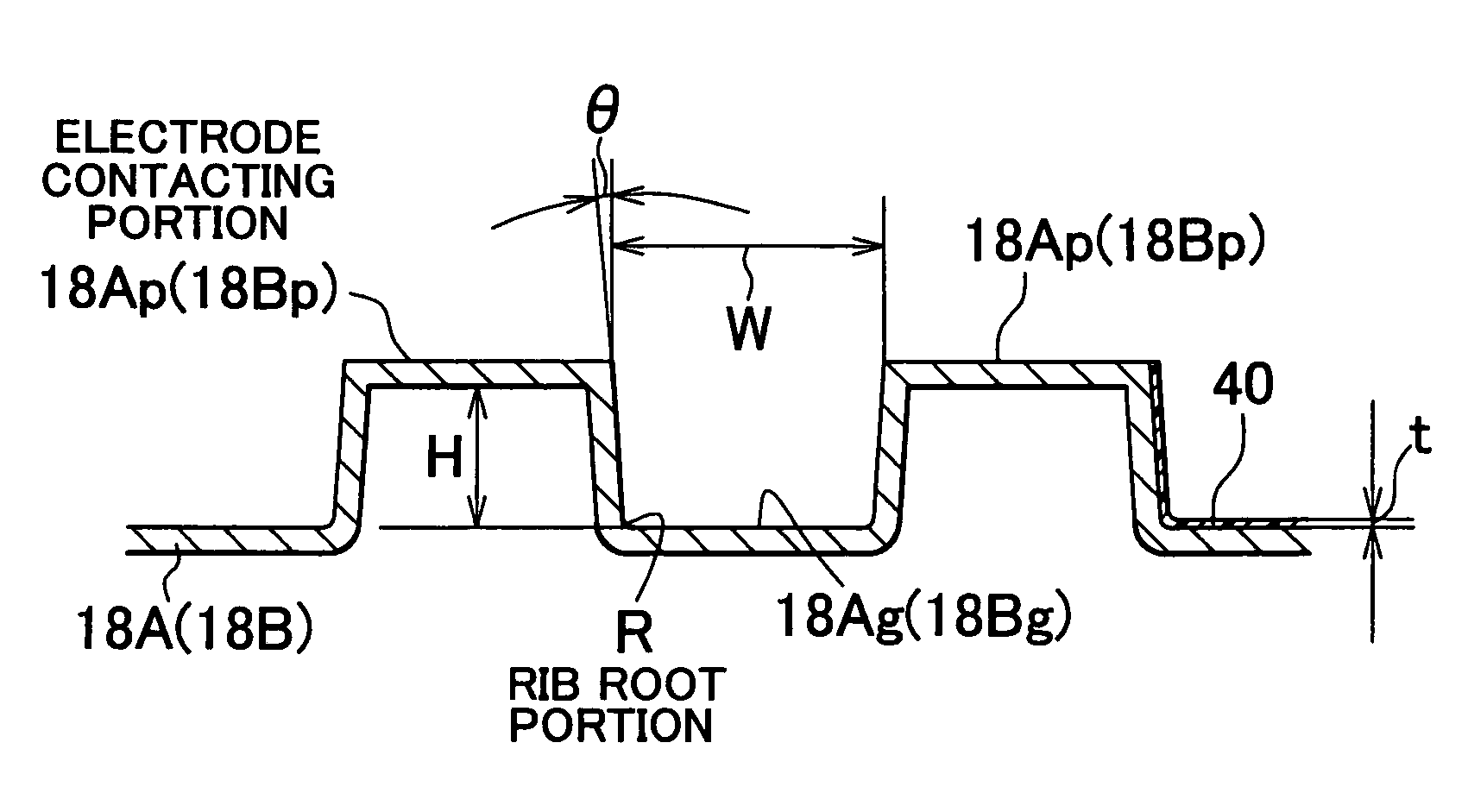
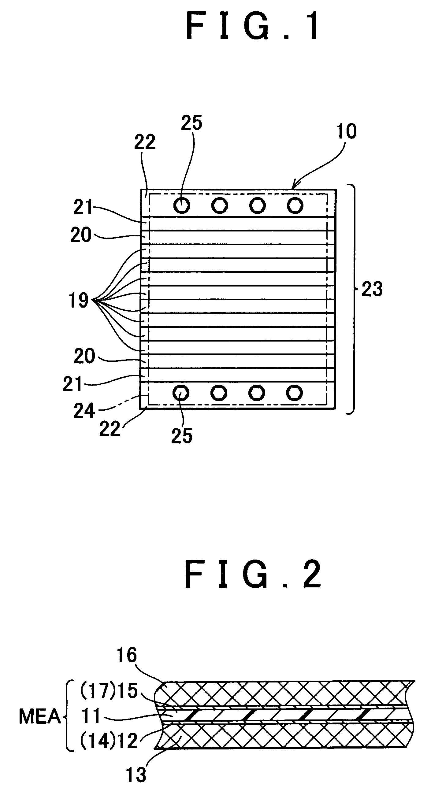
[0030]Hereafter, a separator passage structure of a fuel cell according to the invention will be described with reference to FIG. 1 to FIG. 10. The separator passage structure of a fuel cell according to the invention is applied a proton-exchange membrane fuel cell 10. The fuel cell 10 is mounted, for example, on a fuel cell vehicle. However, the fuel cell 10 may be used for systems other than an automobile.

[0031]A unit cell 19 of the proton-exchange membrane fuel cell is formed by stacking a membrane-electrode assembly (i.e., MEA) and a separator 18, as shown in FIG. 1 to FIG. 10. As shown in FIG. 2, the MEA includes an electrolyte membrane 11 formed of an ion-exchange membrane, an electrode 14 (anode, fuel electrode) formed of a catalytic layer 12 provided on one surface of the electrolyte membrane 11, and an electrode 17 (cathode, air electrode) formed of a catalytic layer 15 provided on the other surface of the electrolyte membrane 11. A diffusion layer 13 is provided between th...


PUM


Abstract

A fuel cell according to an embodiment of the invention includes a separator on which a gas passage groove is formed. A cross sectional area of a gas passage changes in a direction in which the gas passage groove extends, while each of an opening width of the gas passage groove and a depth of the gas passage groove remains substantially constant.

Description

INCORPORATION BY REFERENCE[0001]The disclosure of Japanese Patent Application No. 2003-035273 filed on Feb. 13, 2003 including the specification, drawings and abstract is incorporated herein by reference in its entirety.BACKGROUND OF THE INVENTION[0002]1. Field of the Invention[0003]The invention relates to a separator passage structure of a fuel cell. More particularly, the invention relates to a separator passage structure of a proton-exchange membrane fuel cell.[0004]2. Description of the Related Art[0005]A unit cell of a proton-exchange membrane fuel cell is constituted of a stack body formed by stacking a membrane-electrode assembly (i.e., MEA) and a separator. The MEA includes an electrolyte membrane formed of an ion-exchange membrane, an electrode (i.e., anode, fuel electrode) formed of a catalyst layer which is provided on one surface of the electrolyte membrane, and another electrode (i.e., cathode, air electrode) formed of another catalyst layer which is provided on the ot...

Claims


Application Information

Patent Timeline
IPC IPC(8): H01M2/16H01M2/18H01M2/14H01M8/02H01M8/04H01M8/10H01M8/24
CPCH01M8/0265H01M8/241H01M8/026H01M8/04089Y02E60/50H01M8/2483H01M8/0267Y02P70/50
Inventor MIZUNO, SEIJI
Owner TOYOTA JIDOSHA KK
Learn More