
Optical recording medium

a recording medium and optical technology, applied in the field of optical recording mediums, can solve the problems of insufficient stabilization of recording characteristics under high temperature and high humidity, and achieve the effect of improving the deterioration of recording characteristics

Inactive Publication Date: 2008-12-09
SONY CORP
View PDF19 Cites 0 Cited by
  • Summary
  • Abstract
  • Description
  • Claims
  • Application Information

AI Technical Summary

Benefits of technology

[0024]The present invention provides an optical recording medium capable of suppressing the jitter to enable a satisfactory recording to be performed even when light such as a laser beam of a short wavelength is applied through an objective lens of a high numerical aperture to record information, and further of maintaining a stable and excellent recording characteristic under high temperature and high humidity.
[0029]According to the above-described structure of the present invention, the deterioration of the recording characteristic can be improved well even under high temperature and high humidity. It is assumed that because the optical recording layer made of tin (Sn), nitrogen (N) and oxygen (O) is held between the first and second protective layers, a change in oxygen concentration of the optical recording layer under high temperature and high humidity can be suppressed.

Problems solved by technology

However, when the chemical compound made of tin (Sn), nitrogen (N) and oxygen (O) with non-stoichiometric composition is used for the recording material as described above, the recording characteristic under high temperature and high humidity is not necessarily stabilized sufficiently.

Method used


Image

  • Optical recording medium
  • Optical recording medium
  • Optical recording medium

Examples


example 1

PRACTICE EXAMPLE 1

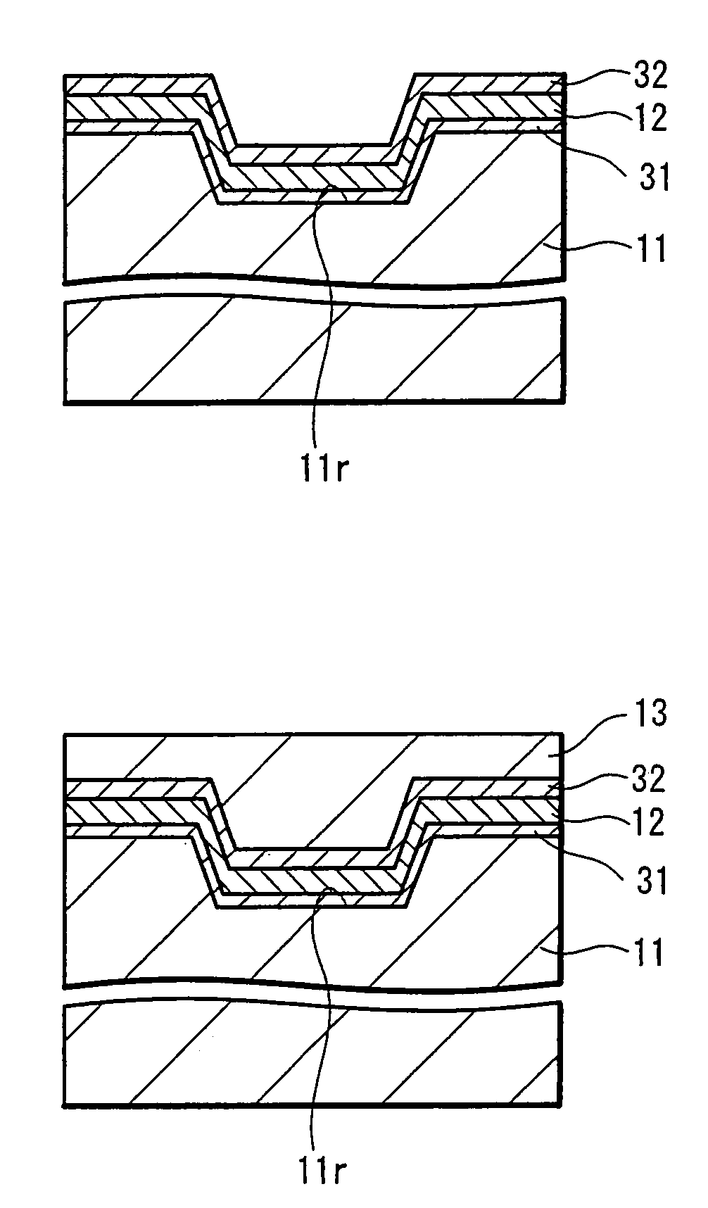
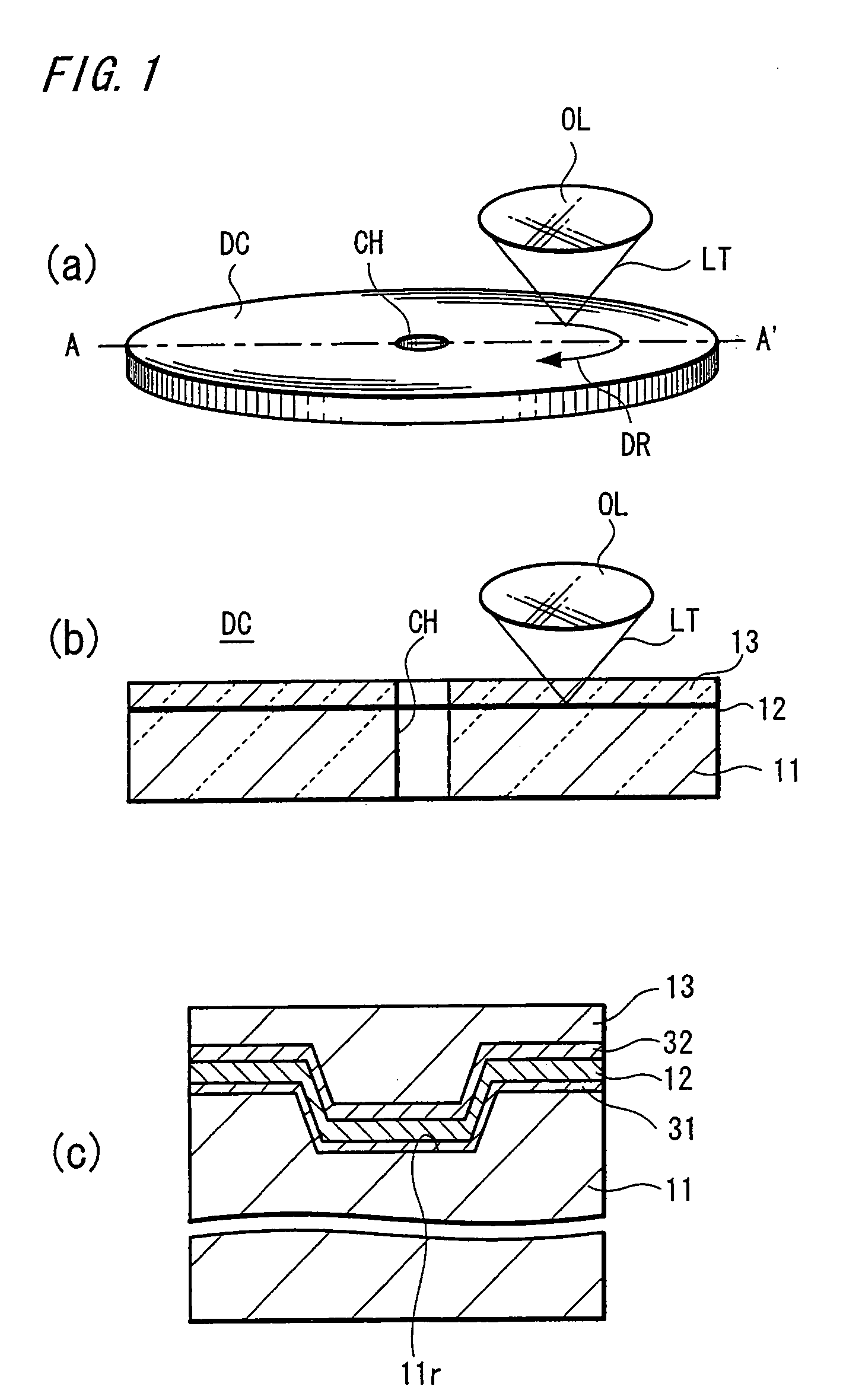
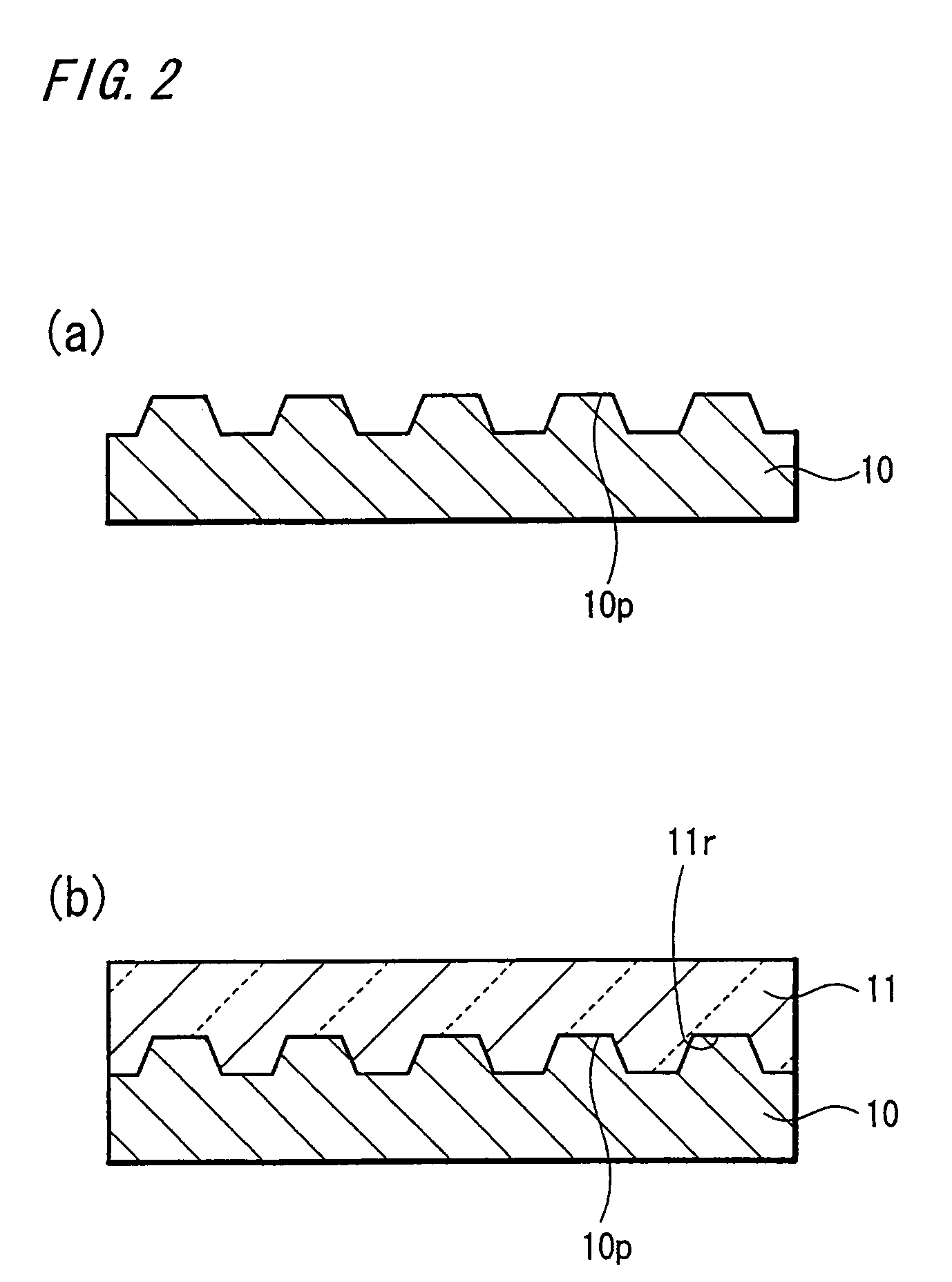
[0082]A disc substrate was prepared, on the surface of which the concave and convex shape dividing the track area was formed. The concave and convex shape was made as a spiral continuous groove with a 0.32 μm pitch, and the depth of the concave and convex shape was made to be 20 nm.

[0083]On the surface of the concave and convex shape thus formed on the disc substrate, the first protective layer 31 was formed by spattering SnO2 with a thickness of 10 nm.

[0084]On the first protective layer 31 was deposited a composition SnxNyox (x=31 atomic %, y=10 atomic %, z=59 atomic %) using a chemical compound composed of tin (Sn), nitrogen (N) and oxygen (O) to have the above composition ratio, with a film thickness of 50 nm to form an optical recording layer.

[0085]Further on that layer was deposited SiO2 with a film thickness of 30 nm to form the second protective layer, and on that layer was formed a light-transmittable layer of 0.1 mm thickness by sticking a film of light-tr...

example 2

PRACTICE EXAMPLE 2

[0093]In the composition SnxNyOz of the optical recording layer 12 in the practice example 1, the composition ratio x, y, z was made to be x=69 atomic %, y=10 atomic %, z=21 atomic %.

[0094]In this optical disc also, no change in jitter was recognized under high temperature and high humidity.

example 3

PRACTICE EXAMPLE 3

[0095]Although the structure is the same as that of the practice example 1, the composition of the optical recording layer was changed into SnxNyOz (x=45 atomic %, y=19 atomic %, z=36 atomic %) to manufacture a sample I of an optical disc.

[0096]In this optical disc also, no change in jitter was recognized under high temperature and high humidity.

[0097]While the above-described practice example has the optical recording layer 12 composed of SnxNyOz, if the optical recording layer 12 is composed of SnxNyOz (30

[0098]In this case...


PUM

PropertyMeasurementUnit
thicknessaaaaaaaaaa
thicknessaaaaaaaaaa
wavelengthaaaaaaaaaa

Abstract

An optical recording medium using Sn as the recording material to improve the jitter is provided, in which on the surface of a disc substrate 11 where a concave and convex shape dividing a track area is formed, are formed on the surface of the concave and convex shape a first protective layer 31 for protecting at least an optical recording layer 31, an optical recording layer 12 using a chemical compound at least composed of tin (Sn), nitrogen (N) and oxygen (O), formed on the first protective layer, a second protective layer 32 for protecting this optical recording layer, formed on this optical recording layer, and a light-transmittable layer 13 formed on the second protective layer; with this structure, the optical recording layer 12 under high temperature and high humidity can be stabilized by means of the first and second protective layers 31 and 32.

Description

[0001]This application claims priority to Japanese Patent Application Number JP2003-068772, filed Mar. 13, 2003 which is incorporated herein by reference.TECHNICAL FIELD[0002]The present invention relates to an optical recording medium, particularly to an optical recording medium capable of high density recording, in which jitter and deterioration of the recording characteristic under high temperature and high humidity are improved.BACKGROUND ART[0003]In recent years, an optical information recording system has widely been studied and developed in the field of information recording.[0004]The optical information recording system has a number of advantages such as can deal with various memory types of non-contact type recording and reproduction, reproduction-only type, write-once type, and rewritable type; and therefore, from industrial use to consumer use, it is contemplated as a system capable of obtaining an inexpensive large-capacity file.[0005]A large capacity of these various op...

Claims


Application Information

Patent Timeline
Patent Type & Authority Patents(United States)
IPC IPC(8): G11B7/24B32B3/02B41M5/26G11B7/24056G11B7/243G11B7/2433G11B7/254G11B7/257
CPCG11B7/243G11B7/257G11B2007/24312G11B2007/2432G11B2007/24322G11B2007/2571G11B7/254
Inventor YASUDA, KOUICHIOYAMADA, MITSUAKINAKANO, JUNMITSUI, NORIOTAMADA, SAKUYA
Owner SONY CORP
Learn More