Optical recording medium having relation between groove depths and pit depths

a technology of optical recording medium and groove depth, which is applied in the direction of mechanical recording, instrumentation, disposition/mounting of heads, etc., can solve the problems of insufficient exposure amount, inability to accurately form the desired photoresist pattern on the master disk, and inability to obtain any sufficient difference in optical path length, etc., to achieve low jitter, high modulation factor, and low jitter

Inactive Publication Date: 2006-01-03
HITACHT MAXELL LTD
View PDF20 Cites 7 Cited by
  • Summary
  • Abstract
  • Description
  • Claims
  • Application Information

AI Technical Summary

Benefits of technology

[0020]In the optical information-recording medium according to the present invention, the in-groove pits, which have the flat bottom surfaces, are arranged on the groove which has the flat bottom surface. Therefore, it is possible to increase the difference between the height position of the interface between the recording layer and the reflective layer at the groove portion at which the recording layer containing the organic dye is formed and the height position of the interface between the recording layer and the reflective layer at the in-groove pit portion, as compared with an optical information-recording medium in which the wide-width portion and the narrow-width portion are formed on the groove. Accordingly, information, which is recorded on the in-groove pits, can be reproduced at a high modulation factor and at a low jitter. Further, it is possible to improve the recording density by narrowing the track pitch, because the wide-width portion is not provided on the groove. In the optical information-recording medium of the present invention, the recording layer containing the organic dye is formed so that dp / dg<Tp / Tg is satisfied by the relationship between the ratio dp / dg between the depth (hereinafter referred to as “in-groove pit depth”) dp ranging from the land surface of the substrate to the bottom surface of the in-groove pit and the depth (hereinafter referred to as “groove depth”) dg ranging from the land surface of the substrate to the bottom surface of the groove and the ratio Tp / Tg between the recess depth Tp of the recording layer at the in-groove pit and the recess depth Tg of the recording layer at the groove. Accordingly, even when the in-groove pit depth dp and the groove depth dg are not formed to have such dimensions that a predetermined signal modulation factor and a radial push-pull signal are obtained, it is possible to increase the difference between the optical path length of the light beam passing through the groove and the optical path length of the light beam passing through the in-groove pit. Therefore, the in-groove pit depth dp can be made shallow as compared with the groove depth dg. Therefore, it is easy to perform the master disk cutting and the formation of the substrate. Further, it is possible to reduce the production cost of the optical information-recording medium. In particular, it is preferable that 1.15<(Tp / Tg) / (dp / dg) is satisfied.
[0021]In the present invention, it is desirable that the ratio Tp / Tg between the recess depth Tg and the recess depth Tp satisfies 1.6≦Tp / Tg≦2.0. Accordingly, information, which is recorded on the in-groove pits, can be reproduced at a high modulation factor and at a low jitter. In the optical information-recording medium of the present invention, for example, it is possible to obtain a modulation factor of not less than 60%, and it is possible to suppress the jitter to be not more than 8%. Therefore, it is possible to obtain reproduction characteristics sufficient for the practical use. Further, it is desirable that the groove depth dg satisfies dg>λ / 4n provided that k represents a wavelength of a light beam to be used for recording or reproduction on the optical information-recording medium, and n represents a refractive index of the substrate. In general, the groove can be detected at the highest contrast when the difference in optical path length between the light beam transmitted through the groove portion and the light beam transmitted through the land portion is λ / 4n. In the case of the optical information-recording medium in which the organic dye material is used for the recording layer, the situation of lamination of the recording layer differs between the groove portion and the land portion. Therefore, in ordinary cases, the difference in optical path length between the light beam transmitted through the groove portion and the light beam transmitted through the land portion is not more than λ / 4n, in which it is impossible to detect the groove at any satisfactory contrast. The optical information-recording medium of the present invention is formed so that the groove depth dg satisfies dg>λ / 4n. Therefore, it is easy to adjust the condition of lamination of the recording layer so that the difference in optical path between the light beam transmitted through the groove portion and the light beam transmitted through the land portion is enlarged to λ / 4n. Accordingly, the groove portion and the land portion can be detected at the highest contrast.
[0038]In the method for producing the optical information-recording medium according to the present invention, the period of time (hereinafter referred to as “blank cutting amount” or “blank period”), in which the photoresist is exposed at the third exposure intensity lower than the first exposure intensity, is provided when the groove exposure step and the in-groove pit exposure step are switched. Therefore, the front end and the rear end of the in-groove pit formation portion in the track direction can be exposed with a sufficient exposure amount, as compared with a case in which the exposure time interval for the in-groove pit formation portion is merely curtailed and shortened before and after the exposure. Accordingly, the photoresist, which is formed on the master disk, is sufficiently photosensitized to arrive at the interface between the photoresist and the master disk. Therefore, when the development treatment is performed, it is possible to form a photoresist pattern corresponding to a desired preformat pattern. When the etching is performed on the basis of the photoresist pattern, it is possible to form a large angle of inclination of the wall surface of the in-groove pit formation portion confronted in the track direction. Accordingly, when the stamper is manufactured on the basis of the master disk, and the stamper is used, then it is possible to manufacture the substrate which has the same concave / convex pattern as the preformat pattern formed on the master disk surface. When a variety of layers including, for example, the recording layer and the reflective layer are formed on the substrate, it is possible to produce the optical information-recording medium which makes it possible to perform the reproduction from the in-groove pits at a high modulation factor and at a low jitter.
[0039]In the present invention, it is desirable that the period of time, in which the exposure is performed at the third exposure intensity, is set on the basis of values of modulation factor, jitter, and radial push-pull of a reproduced signal obtained from the in-groove pits. It is desirable that the blank period is has a value at which the modulation factor of the reproduced signal obtained from the in-groove pits is the local maximum and the maximum. It is desirable that the blank period has a value at which the value of the jitter of the reproduced signal obtained from the in-groove pits is the local minimum and the minimum. The value of the radial push-pull is lowered as the blank period is increased. Further, the three parameters, i.e., the modulation factor, the jitter, and the radial push-pull of the reproduced signal obtained from the in-groove pits are correlated to one another. Therefore, when the blank period of the optimum condition is selected according to the relationship among them, it is possible to optimize the shapes of the in-groove pits and the spaces. Thus, it is possible to obtain the optical information-recording medium having a high recording density with excellent recording and reproduction characteristics and excellent tracking characteristics. In particular, from a viewpoint to obtain the best three parameters, it is desirable that the period of time (blank period), in which the exposure is performed at the third exposure intensity, is 0.2T provided that T represents a clock cycle. Further, the third exposure intensity may be zero.

Problems solved by technology

However, in the case of the optical information-recording medium in which the in-groove pits are formed, when the pit size is decreased by merely lowering the exposure intensity for the in-groove pit formation portion during the exposure of the master disk or when the exposure time for the in-groove pit formation portion is shortened by performing the curtailing before and after the exposure, then the exposure amount is insufficient at the end of the in-groove pit formation portion in the track direction.
For this reason, it is impossible to accurately form the desired photoresist pattern on the master disk.
However, in the optical information-recording medium described above, it is practically impossible to bring about any difference in optical path length of the laser beam to such an extent that a certain signal modulation factor, which is sufficient to reproduce information, is obtained, although the slight difference appears in height position of the interface between the recording layer and the reflective layer between the wide-width portion and the narrow-width portion of the groove.
It was unsuccessful to obtain any sufficient difference in optical path length even by variously changing, for example, the dimension ratio between the wide-width portion and the narrow-width portion of the groove, the viscosity of the recording layer material, and the condition of the rotary driving of the substrate.
Further, it is difficult to narrow the track pitch in the case of the optical information-recording medium on which information such as media information is recorded by utilizing the wide-width portion and the narrow-width portion of the groove as described above.
Therefore, such an optical information-recording medium is especially disadvantageous to increase the recording capacity of the optical information-recording medium by narrowing the track pitch.

Method used


Image

  • Optical recording medium having relation between groove depths and pit depths
  • Optical recording medium having relation between groove depths and pit depths
  • Optical recording medium having relation between groove depths and pit depths

Examples


first embodiment

[0094]An explanation will be made below with reference to FIGS. 5 to 16 about a method for producing an optical information-recording medium according to a first embodiment of the present invention.

[0095]The optical information-recording medium is manufactured by executing a master disk-cutting step of forming a desired pattern on a surface of a master disk, a stamper-manufacturing step of manufacturing a stamper on the basis of the master disk having been subjected to the cutting, a substrate-manufacturing step of replicating a substrate of the optical information-recording medium with the manufactured stamper, and a film-forming step of forming a variety of films on the replicated substrate.

Method for Manufacturing Master Disk and Stamper to Manufacture Substrate

[0096]At first, an explanation will be made with reference to FIGS. 5 to 9 about a method for manufacturing a master disk and a stamper in order to manufacture a substrate 1 of the optical information-recording medium acco...

second embodiment

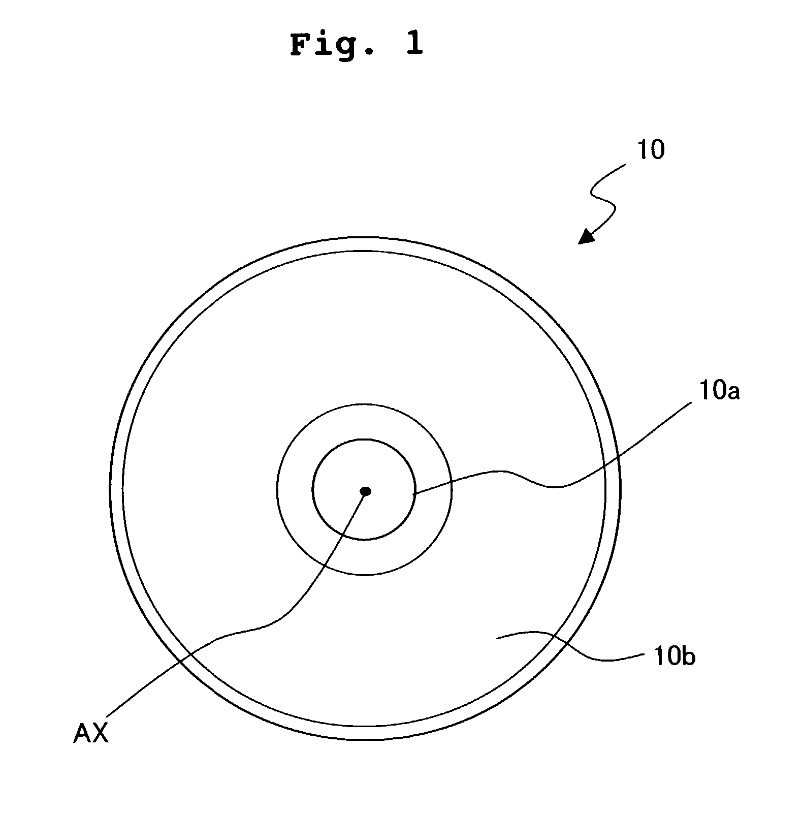
[0114]Next, a second embodiment of the optical information-recording medium of the present invention will be explained with reference to FIGS. 17 to 19. As shown in FIG. 17, an optical information-recording medium of this embodiment was constructed in the same manner as in the first embodiment except that the preformat pattern formation area was composed of a media information-recording area 170b for recording media information and a user recording area 170c for recording user information. The media information-recording area 170b is formed with a groove having in-groove pits. The media information-recording area 170b is formed within a range of radius of 23.9 mm to 24 mm on the basis of the center AX′. On the other hand, the user recording area 170c is formed with only the groove. The user recording area 170c is formed within a range of radius of 21 mm to 23.9 mm and a range of radius of 24 mm to 58 mm on the basis of the center AX′. The groove depth in the user recording area 170c...

modified embodiment 1

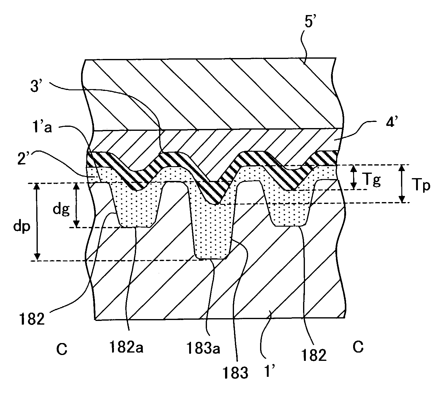
[0117]A modified embodiment of the second embodiment will be explained with reference to FIG. 20. As shown in FIG. 20, the optical information-recording medium of this modified embodiment is an optical information-recording medium comprising a reflective layer 3″, a recording layer 2″, a protective layer 4″, and a cover layer 5″ which are formed in this order on a preformat pattern formation surface of a substrate 1″. Information is recorded and reproduced on the optical information-recording medium by radiating a recording and reproducing laser beam from the side of the cover layer 5″ not from the side of the substrate 1″. Also in the optical information-recording medium, the bottom surface 201a of the groove 201 and the bottom surface 202a of the in-groove pit 202 are formed to be flat. Further, the ratio between the groove depth dg′ and the in-groove pit depth dp′ of the substrate 1″ satisfies the condition of dp′ / dg′201 portion (recess depth of the recording layer ranging from t...


PUM


Abstract

An optical information-recording medium having in-groove pits, which is excellent in recording and reproduction characteristics and tracking characteristics, is provided. A method for producing the optical information-recording medium is also provided. Further, a stamper to be used for producing a substrate for the optical information-recording medium and a method for producing the same are also provided. In the optical information-recording medium of the present invention, the in-groove pits, which have flat bottom surfaces, are arranged on a groove which has a flat bottom surface. Therefore, it is possible to increase the difference between a height position of an interface between a recording layer and a reflective layer at a groove portion formed with the recording layer containing an organic dye and a height position of the interface between the recording layer and the reflective layer at an in-groove pit portion, as compared with an optical information-recording medium in which a wide-width portion and a narrow-width portion are formed on a groove. Accordingly, information, which is recorded on the in-groove pits, can be reproduced at a high modulation factor and at a low jitter.

Description

BACKGROUND OF THE INVENTION[0001]1. Field of the Invention[0002]The present invention relates to an optical information-recording medium and a method for producing the same as well as a stamper to be used for producing a substrate of the optical information-recording medium and a method for producing the same. In particular, the present invention relates to an optical information-recording medium on which media information such as a name of manufacturer and information concerning copyright protection measures is recorded on a groove in a form of prepits and a method for producing the same as well as a stamper to be used for producing a substrate thereof and a method for producing the same.[0003]2. Related Art[0004]In recent years, DVD (digital versatile disk), which has a recording capacity several times that of CD (compact disk), is widely used as an information-recording medium, for example, for images and voices. In relation to DVD, those having been commercially available as pro...

Claims


Application Information

Patent Timeline
IPC IPC(8): G11B11/00G11B7/007G11B7/09G11B7/26
CPCG11B7/00736G11B7/261G11B7/24079G11B7/0938
Inventor SUENAGA, MASASHITAKAHASHI, YUSUKE
Owner HITACHT MAXELL LTD
Why Eureka
Try Eureka