
Materials for freezing light

a material and light technology, applied in the field of materials for freezing light, can solve the problems of inability to meet the requirements of natural occurring dielectric materials, inability to meet materials for other frequency ranges, and inability to freeze materials,

Inactive Publication Date: 2008-12-09
CLEMSON UNIV RES FOUND +1
View PDF8 Cites 5 Cited by
  • Summary
  • Abstract
  • Description
  • Claims
  • Application Information

AI Technical Summary

Benefits of technology

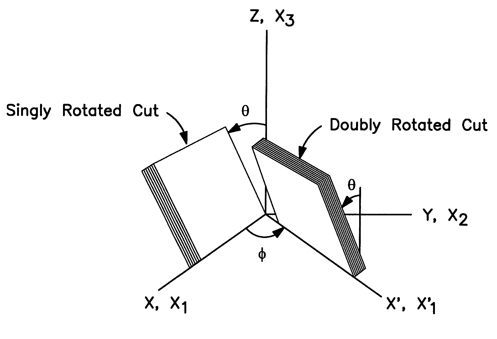
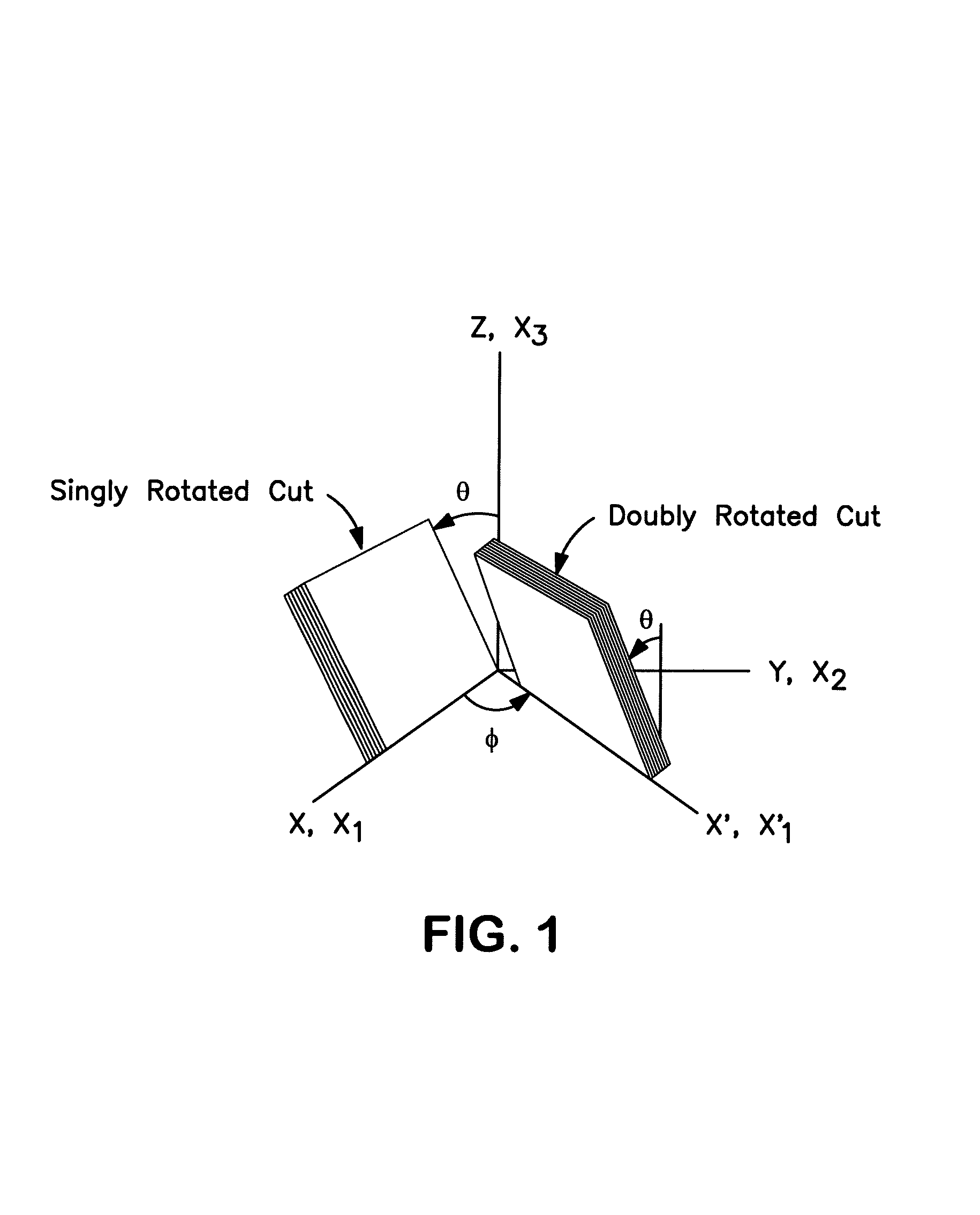
[0011]The methods of the present invention can also include applying a force or an energy field to the multi-layered structure. For example, a mechanical force, an electrical field, a magnetic field, a thermal field, or a combination thereof can be applied to the structure. This application of a force or energy field can alter the permittivity contrast between the first layer and the second layer. Thus, the application of the force or energy field can create the canted geometric axis and / or can alter the geometric axis through alteration of the permittivity contrast between the two layers, providing tunability to the devices. Moreover, the force and / or energy field can be dynamic, which can cause the induced anisotropic permittivity to likewise be dynamic.

Problems solved by technology

Unfortunately, few naturally occurring dielectric materials meet the criteria including having off-diagonal ε elements so as to satisfy the permittivity requirement of the media disclosed in Figotin, et al.
The patent discloses that some generic ferrite materials are available for use with microwave, millimeter wave, or submillimeter wave ranges, but discloses no possible materials for other frequency ranges.
In fact, it has been taught that at infrared and optical frequency ranges, finding appropriate materials for use in forming such media is highly problematic, and at frequencies above 1012 Hz, frozen mode formation has been considered to be impractical (see, for example, ‘Oblique frozen modes in periodic layered media’, A. Figotin and I. Vitebskiy, Physical Review E, 68, 036609 (2003)).

Method used


Image

  • Materials for freezing light
  • Materials for freezing light
  • Materials for freezing light

Examples


Embodiment Construction

[0023]Reference will now be made in detail to various embodiments of the invention, one or more examples of which are illustrated in the accompanying Figures. Each example is provided by way of explanation of the invention, not limitation of the invention. In fact, it will be apparent to those skilled in the art that various modifications and variations can be made in the present invention without departing from the scope or spirit of the invention. For instance, features illustrated or described as part of one embodiment, can be used on another embodiment to yield a still further embodiment. Thus, it is intended that the present invention cover such modifications and variations as come within the scope of the appended claims and their equivalents.

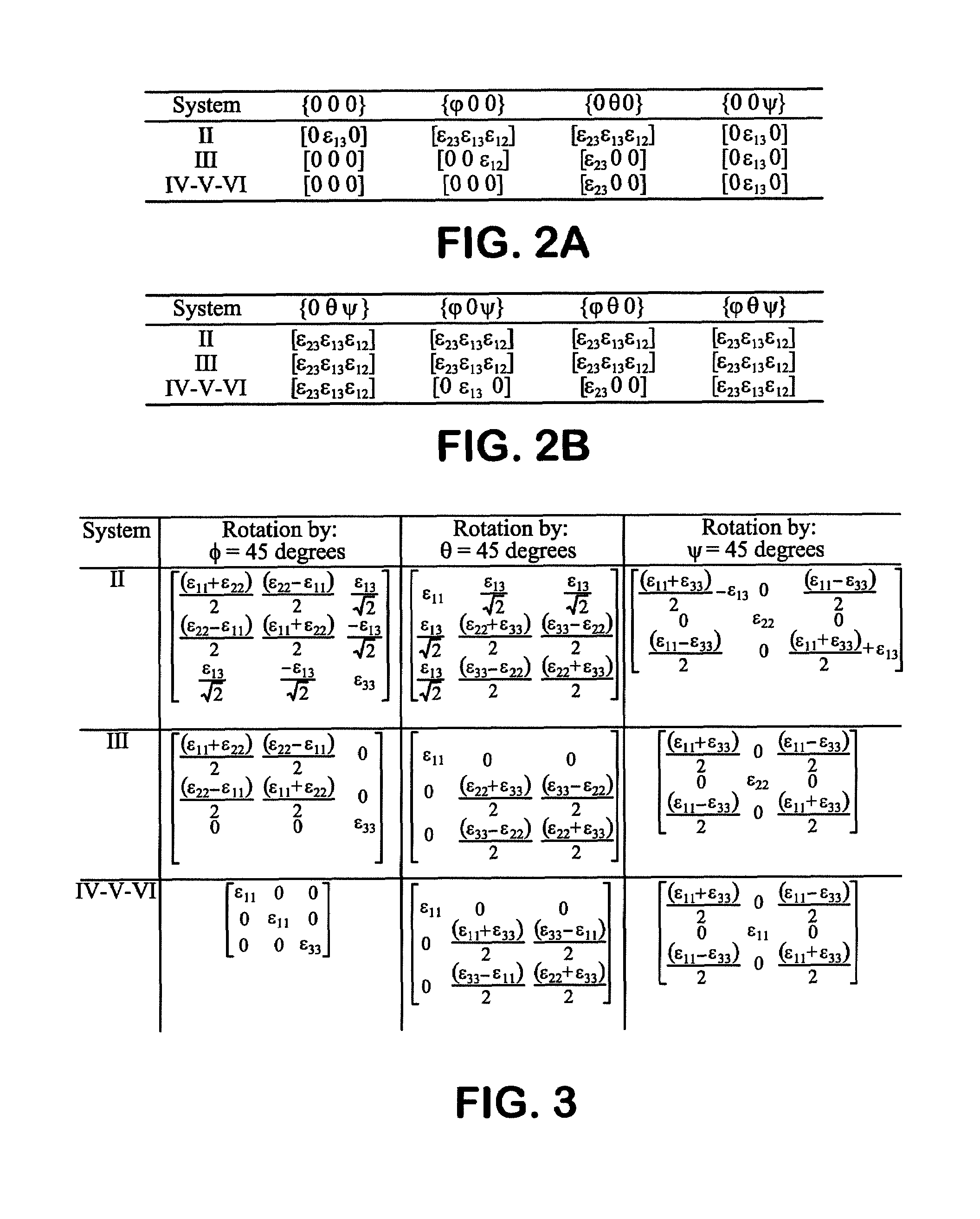
[0024]For purposes of this disclosure, it should be understood that IEEE conventions for specifying crystallographic axes, rotations about the axes, and ε as the off-diagonal element for the monoclinic classes has been utilized. Such conve...


PUM

PropertyMeasurementUnit
frequenciesaaaaaaaaaa
depthaaaaaaaaaa
refractive indexaaaaaaaaaa

Abstract

Recent theoretical investigations have predicted the existence of axially frozen modes that arise when light is incident upon an anisotropic two-dimensional photonic crystal. Such electromagnetic modes are of interest since they suggest a near-zero group velocity with extraordinary amplitudes. The present invention addresses the crystal physics associated with realizing such effects and provides for the development of materials suitable for use in the forming photonic crystals that can exhibit such effects.

Description

CROSS REFERENCE TO RELATED APPLICATIONS[0001]This application claims benefit to U.S. Provisional Patent Application Ser. No. 60 / 645,292 filed Jan. 20, 2005.STATEMENT OF GOVERNMENT SPONSORED RESEARCH[0002]The captioned invention was made with Government support under N66001-03-1-8900 awarded by the Office of Naval Research. The Government has certain rights in this inventionBACKGROUND OF THE INVENTION[0003]Photonic crystals are structures that possess spatial periodicities in refractive index, which lead to allowed and forbidden directions for light of certain energy and polarization to propagate. They have been the subject of considerable research and development efforts around the world due to their potential for controlling light in ways that cannot be achieved using homogeneous structures. Examples of extraordinary optical phenomena enabled by photonic crystals include reversed Doppler shifts, divergent-less super-lenses, negative refraction, and huge Verdet constants, to name ju...

Claims


Application Information

Patent Timeline
Patent Type & Authority Patents(United States)
IPC IPC(8): G02F1/13G02B5/18
CPCG02B5/3083G02F1/00G02F2202/32
Inventor BALLATO, ARTHURBALLATO, JOHN
Owner CLEMSON UNIV RES FOUND
Learn More