
Methods for formation of antenna array using asymmetry

a technology of antenna array and symmetry, applied in the field of wireless communication, can solve the problems of poor isolation lack of flexibility of switching between rhcp and lhcp, and inability to track multiple objects simultaneously

Active Publication Date: 2020-05-12
TIONESTA
View PDF13 Cites 9 Cited by
  • Summary
  • Abstract
  • Description
  • Claims
  • Application Information

AI Technical Summary

Benefits of technology

The patent describes an antenna system that has multiple antenna elements arranged in an asymmetrical way to improve its performance. Each antenna element can receive both vertically and horizontally polarized signals, which are then combined using a processing circuit to create a left-hand or right-hand circularly polarized signal. The antenna system is designed to focus its beam in a specific direction. The asymmetrical positioning and orientation of the antenna elements allows for tunability, meaning that the system can be optimized for different parameters to achieve the best performance. The method for optimizing the antenna system includes off-line computing and a lookup table to determine the best pattern for a given input vector. Overall, the patent describes an improved antenna system that can focus its beam in a specific direction for better performance.

Problems solved by technology

Conventional solutions lack flexibility of switching between RHCP and LHCP, poor isolation between RHCP and LHCP, inability of tracking multiple objects simultaneously, and poor signal-to-noise ratio due to inability of implementing maximum ratio combining.

Method used


Image

  • Methods for formation of antenna array using asymmetry
  • Methods for formation of antenna array using asymmetry
  • Methods for formation of antenna array using asymmetry

Examples


case ii

[0174]Use Maritime Field Environment

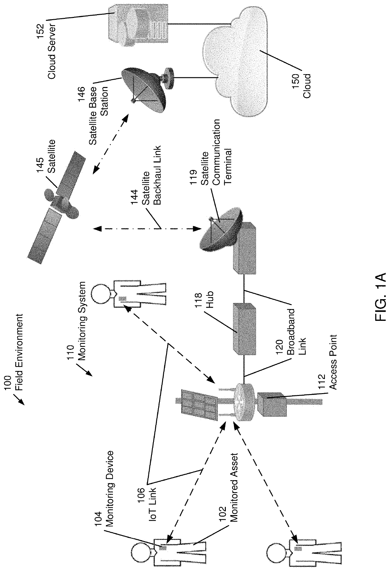
[0175]In one or more embodiments of the invention, the field environment may be an ocean going vessel (e.g., an off-shore drilling rig, a cargo container, or cruise ship) without no externally accessible communication infrastructure (e.g., no cellular network at sea). The satellite communication terminal may be used to establish a local network to facilitate communication between personnel and equipment within the field environment and / or to establish communication with other external networks around the world.

[0176]For example, on a container ship, a satellite communication terminal may establish broadband links with laptops operated by crew members and monitoring devices attached to cargo containers. The local network maintained by the satellite communication terminal on the container ship may allow the crew members, with proper authorization, communicate with each other via broadband link or access information from the monitoring devices via I...


PUM


Abstract

An antenna system comprises a plurality of antenna elements arranged asymmetrically in an antenna array. Each antenna element in the antenna system includes one or more first terminals that receive a vertically polarized wireless signal and one or more second terminals that receive horizontally a polarized wireless signal. The antenna system further comprises a processing circuit that combines the vertically polarized signal and the horizontally polarized signal using a combiner after applying a 90-degree phase shift to the vertically polarized signal or the horizontally polarized signal to obtain a left-hand circularly polarized (LHCP) signal or a right-hand circularly polarized (RHCP) signal. The antenna system is configured to steer a beam of the antenna array to best antenna pattern. The plurality of antenna elements are asymmetrically positioned and asymmetrically oriented in the antenna array to provide tunability to each antenna element.

Description

BACKGROUND OF INVENTIONField of the Invention[0001]The invention generally relates to wireless communication. More specifically, the invention relates to using an antenna system to receive and process wireless communication signals transmitted from satellites.Background Art[0002]A growing number of broadband satellite constellations are being launched to support communication networks around the world, even in the most remote field environments. Remote field environments often have minimal or no satellite networking infrastructure to interact with these satellite constellation. Accordingly, a satellite communication terminal that communicates with satellites in orbit and that established and maintains a local network on the ground may be beneficial users operating in or travelling across the field environment. Furthermore, a satellite communication terminal that provides access to the internet, a cloud computing platform, a sensor network, or a monitoring system may be beneficial or...

Claims


Application Information

Patent Timeline
Patent Type & Authority Patents(United States)
IPC IPC(8): H01Q3/38H01Q1/52H01Q21/28H04B7/08H01Q21/22H01Q13/08H01Q21/06H01Q3/26
CPCH01Q21/22H01Q1/523H01Q21/065H01Q3/38H04B7/084H04B7/10H04B7/086H04B7/1851H04B7/18517H01Q9/0435H01Q9/0478H04B7/0469
Inventor STRUHSAKER, PAULPOSNER, PAULPASAND, ALI SAHEBKHANDANI, AMIR KEYVAN
Owner TIONESTA
Learn More