Handheld electronic test probe assembly

a technology of electronic test probes and assembly parts, which is applied in the direction of electrical testing, measurement devices, instruments, etc., can solve the problems of inability to adjust, adversely affect electrical contact resistance and test, and ineffectiveness, so as to reduce the tendency to launch chips, improve ergonomics, and improve the effect of chip pickup and retention

Inactive Publication Date: 2008-11-25
CERAMIC COMPONENT TECH
View PDF14 Cites 14 Cited by
  • Summary
  • Abstract
  • Description
  • Claims
  • Application Information

AI Technical Summary

Benefits of technology

[0009]This invention addresses the need outlined above by providing an electronic test probe assembly that includes a handheld piece and a combination of components on the handheld piece that function as an electronic test probe. According to one aspect of the invention, the handheld piece (hereinafter referred to as a “probe-supporting component”) takes the form of a housing in which the combination of test probe components (hereinafter referred to as a “test probe”) is partially disposed. Two test probe legs extend out of the housing to spaced-apart distal end portions of the legs, with the housing enhancing leg stability and limiting leg contact for less stray impedance influence on test results when a user holds the housing and squeezes the distal end portions toward terminals on a device under test (DUT).
[0014]Thus, the invention alleviates some drawbacks of existing tweezers-type electronic test probes. It provides true four-wire Kelvin contacts all the way to the surface of the DUT terminals for low impedance applications, and fully guarded, coaxial construction for high impedance applications. The robust, production-worthy construction promises reliability and long life. Parallel, DUT-gripping test probe electrodes significantly reduce the tendency to launch chips. The test probe assembly is suitable for various common chip sizes, and it is ergonomically improved with superior chip pickup and retention that reduces user frustration over lost chips. The above features result in superior electrical and mechanical performance. The following illustrative drawings and detailed description make the foregoing and other objects, features, and advantages of the invention more apparent.

Problems solved by technology

Although existing tweezers-type electronic test probes are convenient to use in some respects, they have some accompanying drawbacks.
Mechanically, the legs are often not very stable.
As a result, the electrodes on the distal ends of the legs move sideways relative to the terminals on a DUT being held, and that movement can adversely affect electrical contact resistance and test results.
That arrangement results in uncertain contact resistance; it results in an uncertain effective serial resistance (ESR) that adversely affects test results.
Separate Kelvin-type sense and drive lines are provided for each electrode, but they do not achieve true Kelvin measurement because both sense and drive lines are connected to the same electrically conductive element so that they are connected together on the test instrument side of the ESR.
As a result, drive current flowing through the ESR affects measurements made using the sense lines.
Moreover, the entire existing tweezers-type electronic test probe fails to guard against stray serial impedance (SSI) and other stray impedances introduced by the top of a test bench, other nearby objects, and the user's hand gripping the tweezer legs.

Method used


Image

  • Handheld electronic test probe assembly
  • Handheld electronic test probe assembly
  • Handheld electronic test probe assembly

Examples


second embodiment

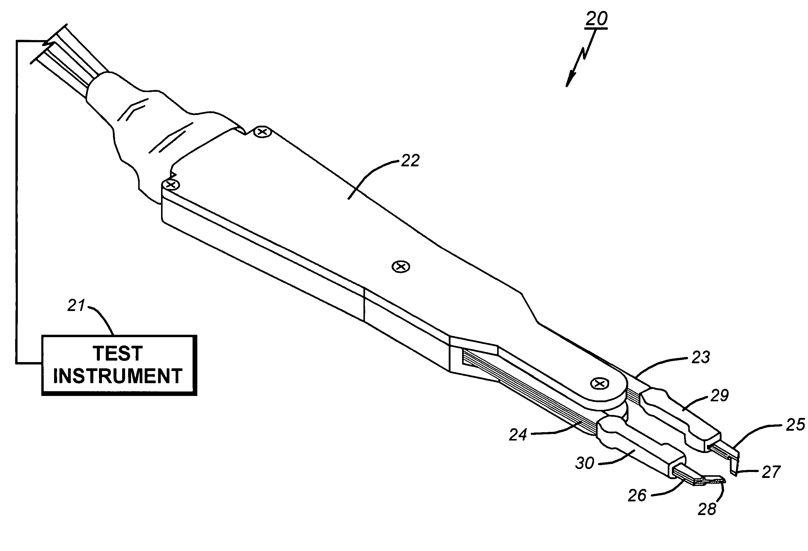
[0042]FIG. 11 shows a test probe assembly 100 that embodies some variations. The test probe assembly 100 is similar to the test probe assembly 20 in many respects and so only major differences are described in greater detail. For convenience, reference numerals designating parts of the test probe assembly 100 are increase by one hundred over those designating similar, corresponding, or related parts of the test probe assembly 20.

[0043]Similar in some respects to the test probe assembly 20, the test probe assembly 100 includes first and second layered test probe legs 123 and 124 that extend to first and second distal end portions 125 and 126 of the legs. The major differences is that the test probe assembly 100 includes three electrodes 127, 128, and 160, instead of just the two electrodes 27 and 28 illustrated for the test probe assembly 20. This configuration enables use of the test probe assembly 100 for testing a three-terminal DUT 116 having at least three terminals 116A, 116B, ...


PUM


Abstract

A test probe assembly includes a probe-supporting component and a test probe on it. According to one aspect of the invention, the probe-supporting component takes the form of a probe-supporting housing in which the test probe is partially disposed so that two test probe legs extend out of the housing to spaced-apart distal end portions of the legs, with the housing enhancing leg stability and limiting leg contact for less stray-impedance influence on test results when a user holds the housing and squeezes the distal end portions toward terminals on a device under test (DUT). According to another aspect, at least one of the distal end portions includes a terminal-contacting electrode having at least two electrically conductive elements for contacting a terminal on the DUT, each electrically conductive element being moveable to and from the terminal independent of the other element for multi-point contact (MPC) purposes resulting in reduced effective serial resistance (ESR) and enabling true Kelvin-type measurements. The legs are preferably composed of a plurality of thin, flat, laser-machined layers, and one alternate embodiment includes at least three terminal-contacting electrodes for use with a three-terminal DUT.

Description

BACKGROUND OF THE INVENTION[0001]1. Technical Field[0002]This invention relates generally to the field of electronic test equipment, and more particularly to a handheld electronic test probe assembly for testing miniature electronic circuit components, including passive, ceramic capacitors, resistors, inductors, and the like.[0003]2. Description of Related Art[0004]A typical tweezers is a handheld object used for any of various tasks for which it is designed, including plucking, holding, or manipulating an object. It includes two spring-biased legs having proximal ends that are joined together and opposing distal end portions that are spaced apart. A user grasps the tweezers in one hand and squeezes it in order to move the distal end portions of the legs toward each other so that they bear against an object of interest.[0005]A “tweezers-type” electronic test probe is similar in that it is a handheld object having first and second legs that the user grasps and squeezes. As the user s...

Claims


Application Information

Patent Timeline
Patent Type & Authority Patents(United States)
IPC IPC(8): G01R31/02
CPCG01R1/06788
Inventor SAULNIER, CHRISTIAN R.GASQUE, JAMES G.
Owner CERAMIC COMPONENT TECH
Why Eureka
Try Eureka