
Method for removing coating from power unit components and device for carrying out the method

a technology for power units and components, applied in the direction of metallic material coating process, chemical vapor deposition coating, fluid pressure measurement, etc., can solve the problems of base material, partially removed or chemically attacked, and achieve the effect of substantially more convenient implementation

Inactive Publication Date: 2008-11-18
MTU AERO ENGINES GMBH
View PDF22 Cites 24 Cited by
  • Summary
  • Abstract
  • Description
  • Claims
  • Application Information

AI Technical Summary

Benefits of technology

[0010]The method for removing coatings—e.g., metallic coatings—from power unit components may provide a number of advantages. Thus, disadvantages of the ecologically and economically doubtful wet chemical methods do not apply. Optimization and precise determination of the material removal may be possible by the constant process monitoring via the spectrometer, and may be able to be implemented in an economical manner, which may lead to better quality assurance and shortening of production cycle times. The spectrometer analyzes the light emission caused by the irradiated laser or plasma radiation. The radiation is characteristic for the material removed. Since when using the high-energy plasma-pulse method, in contrast to the laser, in each case an area of up to a few square centimeters is acted upon and stripped simultaneously, the coating-removal process may be performed extremely efficiently.
[0013]Removal of material from the base material of the component to be stripped may thereby be avoided with great reliability. Furthermore, occupational safety and health measures may be implemented substantially more easily than when working with removal methods using wet chemicals.

Problems solved by technology

When removing these coatings by wet chemical processes, the danger exists that upon reaching the base material, it will be partially removed or chemically attacked, because the base material and the coating are very similar in their chemical composition.
An attack on the base material during coating removal using wet chemical processes is not even avoidable by process analytics, since the extent of unwanted surface removal is only determinable using measuring-technique measures after the stripping process has ended, so that it is necessary to restrict the frequency of coating removal when using these methods.
Moreover, such wet chemical processes are ecologically dangerous.
They require a high expenditure for the necessary occupational safety and health measures and the disposal of the process agents in a manner compatible with the environment.
Thus, disadvantages of the ecologically and economically doubtful wet chemical methods do not apply.

Method used


Image

  • Method for removing coating from power unit components and device for carrying out the method
  • Method for removing coating from power unit components and device for carrying out the method

Examples


Embodiment Construction

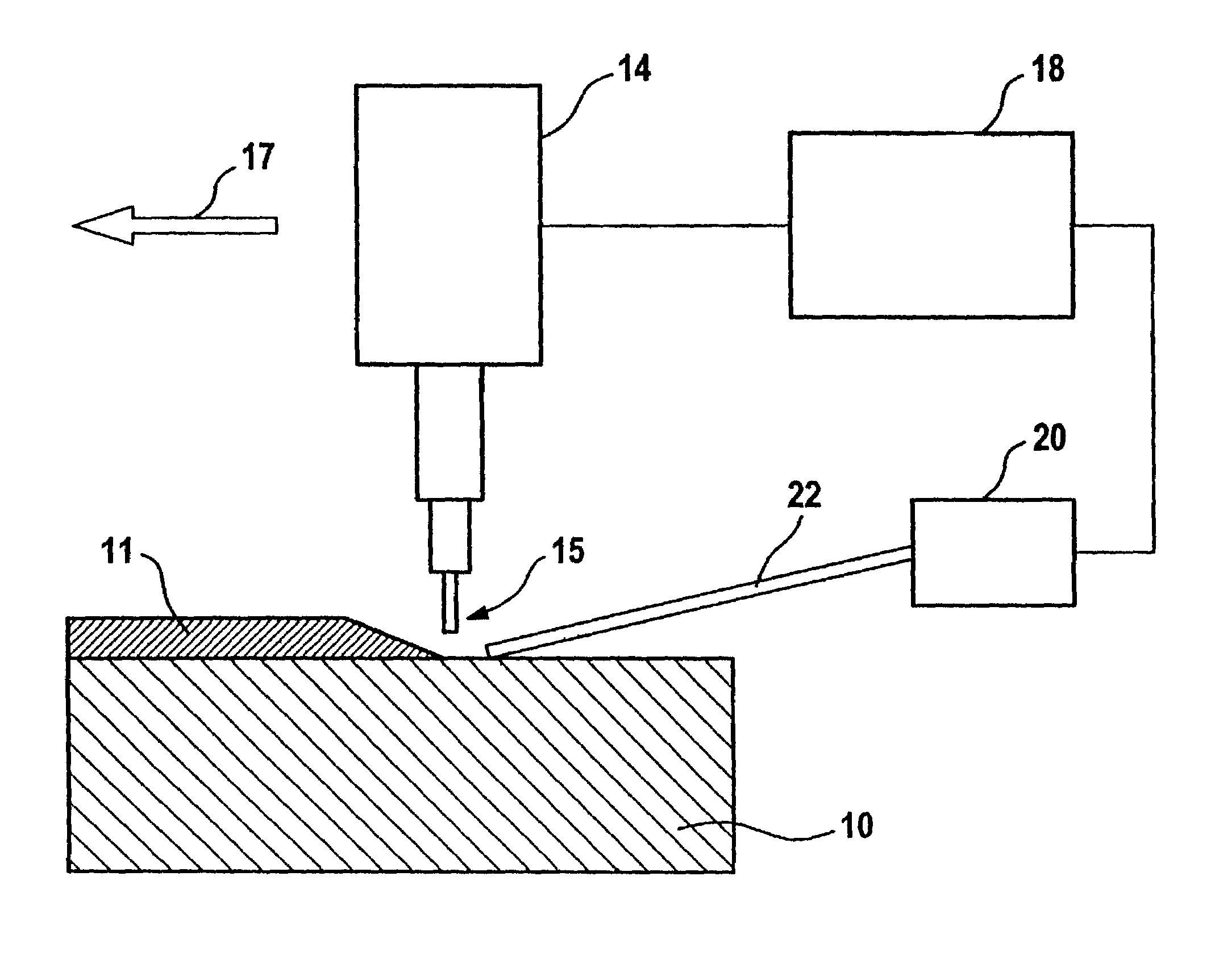
[0016]A suitably clamped power unit component 10, e.g., a turbine blade, made of a nickel-based alloy, has a single-layer or multilayer coating 11 made of a layer of the type MCrAlY that is resistant to hot-gas corrosion, and a ceramic ZrO2 heat-insulating layer. An energy source 14 is assigned a beam head (laser or plasma source) 15 having the exit window of the high-energy radiation, the beam head being movable in the direction of arrow 17—the feed or advance direction.

[0017]Also allocated to energy source 14 is a control unit 18, having a computer, for regulating the energy output, which is connected to a spectrometer 20. A fiber line 22 may be used as a coupling element between coating 11 to be removed and spectrometer 20.

[0018]Depending on the application, the energy source may take the form, for example, of a laser energy source or a high-energy plasma-pulse source.

[0019]The layers to be removed have differences in their chemical composition with respect to the material of the...


PUM

PropertyMeasurementUnit
Concentrationaaaaaaaaaa
Spectrumaaaaaaaaaa

Abstract

A method for the selective removal of one or more layers from a power unit component, e.g., a turbine blade of a heavy-duty turbine, using high-energy radiation of such a wavelength that the supplied energy is so strongly absorbed by the layer to be removed in each case that the removal threshold of the specific material of the layer to be removed is exceeded, while this removal threshold is not reached in the subsurface to be preserved, a spectrometer connected to a control unit via a light-conducting fiber cable such that the method-specific characteristic values are determinable by spectroscopic methods during the removal of the respective layer and are used for the self-regulating process limitation.

Description

CROSS-REFERENCE TO RELATED APPLICATIONS[0001]The present application claims priority to Application No. 102 10 518.9, filed in the Federal Republic of Germany on Mar. 9, 2002, which is expressly incorporated herein in its entirety by reference thereto.FILED OF THE INVENTION[0002]The present invention relates to a method for removing coating from power unit components and a device for carrying out the method.BACKGROUND INFORMATION[0003]After predefined operating times, power unit components, particularly of heavy-duty power units such as turbine blades, produced in composite construction must be stripped down to the base material, to be able to subsequently recoat it for further use.[0004]Conventionally, the coating is removed using wet chemical processes. The base materials of such turbine blades are nickel-based, cobalt-based and titanium-based alloys, while the coatings to be applied are made of corrosion-resistant nickel-aluminum alloys, nickel-chromium-aluminum alloys, MCrAlY al...

Claims


Application Information

Patent Timeline
IPC IPC(8): B44C1/22G01L21/30B08B7/00B23K26/40C23F4/00C23F4/02C23G5/00
CPCB08B7/0035B08B7/0042B23K26/365B23K26/401B23K26/4015B23K26/408B23K26/4095C23F4/00C23F4/02C23G5/00B23K26/40B23K26/361B23K2101/34B23K2101/35B23K2103/08B23K2103/26B23K2103/50B23K2103/52
Inventor BAYER, ERWINGOLD, KARSTENPLATZ, ALBINSCHMIDT, MATTHIAS
Owner MTU AERO ENGINES GMBH
Learn More