
Heat dissipating device with heat reservoir

a heat dissipating device and heat reservoir technology, which is applied in semiconductor devices, lighting and heating apparatus, cooling/ventilation/heating modifications, etc., can solve the problems of fan generating a sudden variation of noise level, cpu overheating and damage, and user's annoying computer user, etc., to achieve high heat dissipation efficiency, reduce the effect of temperature drop, and high thermal conductivity

Inactive Publication Date: 2008-11-11
HON HAI PRECISION IND CO LTD +1
View PDF17 Cites 7 Cited by
  • Summary
  • Abstract
  • Description
  • Claims
  • Application Information

AI Technical Summary

Benefits of technology

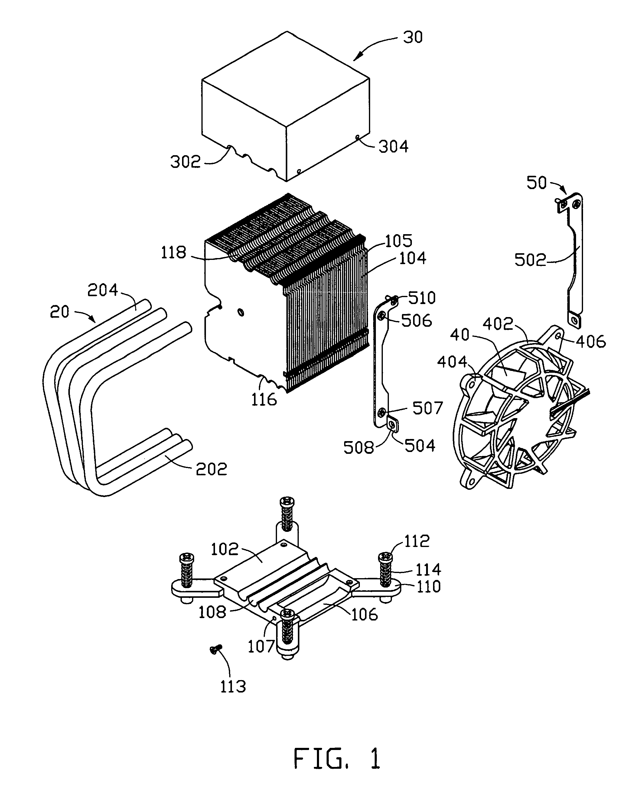
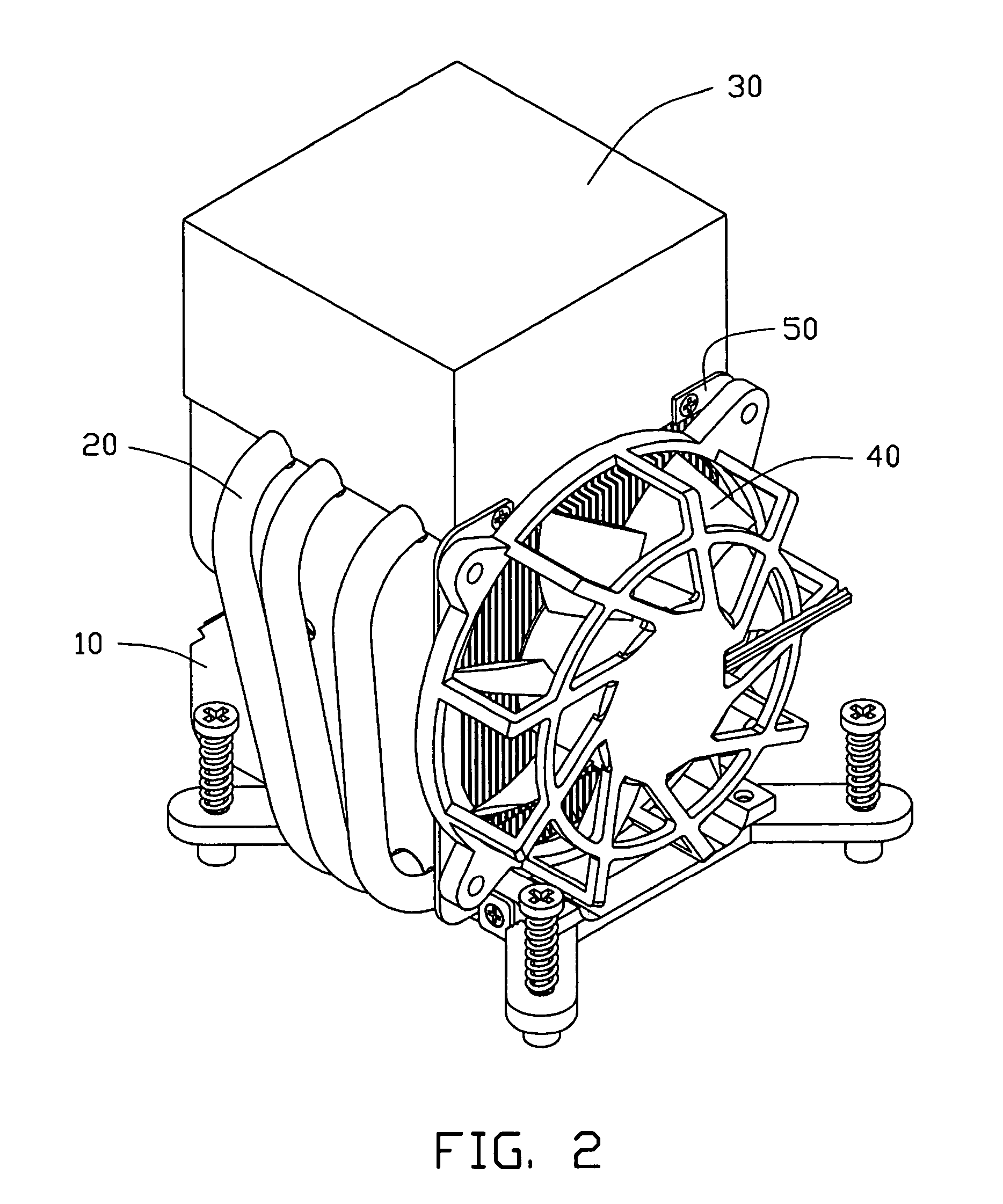
The present invention is a heat dissipating device that has a uniform heat dissipation effect. It includes a heat sink, U-shaped heat pipe, heat reservoir, and fan. The heat sink has a heat spreader and fins, while the heat pipe has an evaporating portion and a condensing portion. The heat reservoir has a high thermal conductivity and contains a working medium to absorb and release heat. This allows the device to maintain a stable temperature range for the CPU. The technical effect of this invention is to provide a heat dissipating device that can effectively control the temperature of the CPU to prevent overheating or sudden changes in temperature.

Problems solved by technology

Without proper cooling, the heat generated by the CPU can quickly cause the CPU to overheat and damage the CPU.
The sudden change of the temperature of the CPU is harmful to the lifespan of the CPU.
The abrupt variation of the speed of the fan according to the change of temperature of the CPU leads the fan to generate a suddenly varied noise level which is very annoying to a user of the computer.

Method used


Image

  • Heat dissipating device with heat reservoir
  • Heat dissipating device with heat reservoir
  • Heat dissipating device with heat reservoir

Examples


first embodiment

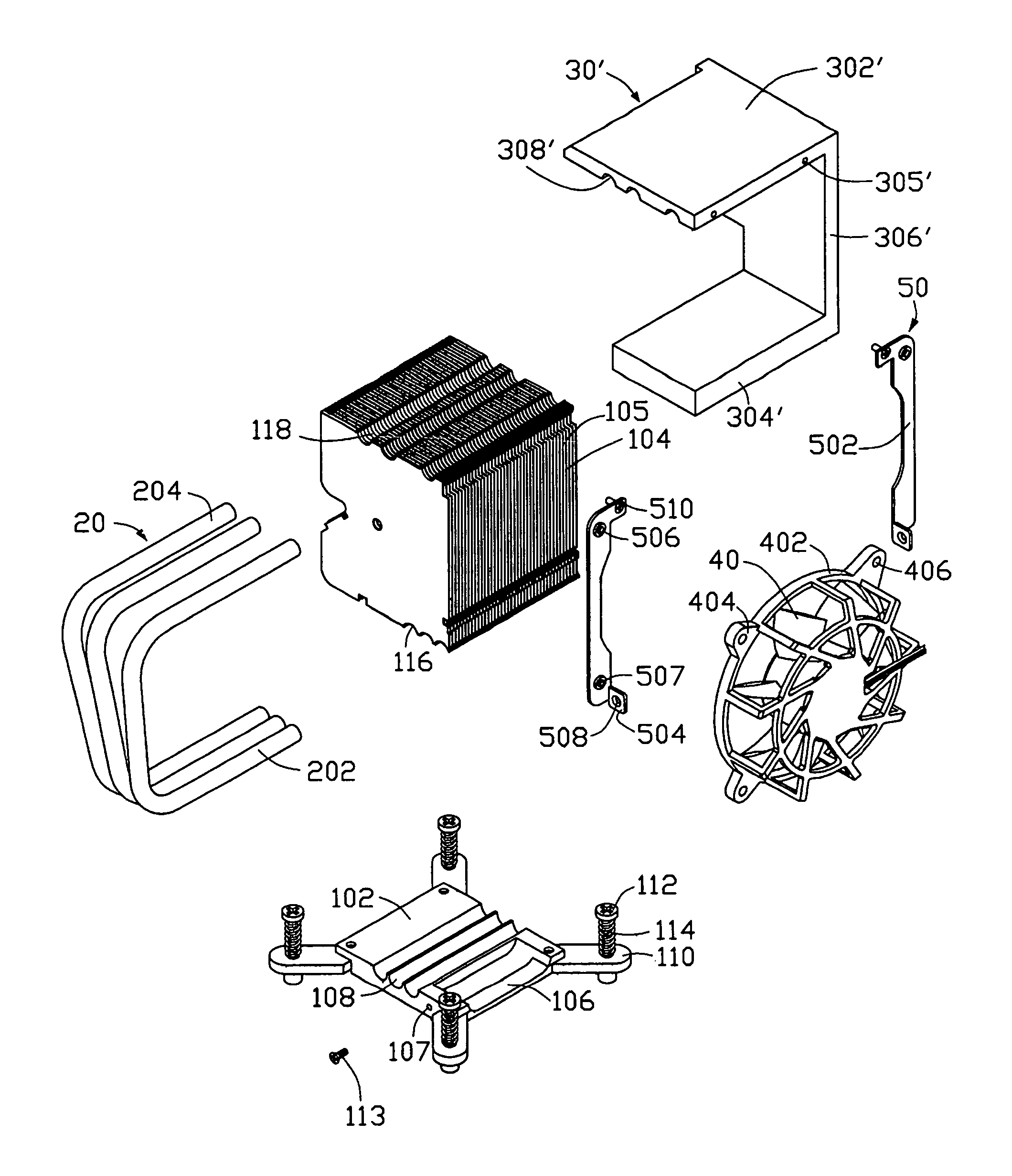
[0029]FIGS. 3-4 show a heat dissipating device in accordance with a second preferred embodiment of the present invention. The heat dissipating device of the second preferred embodiment is similar with that of the first preferred embodiment. However, a heat reservoir 30′ replaces the heat reservoir 30 of the The heat reservoir 30′ has a U-shaped configuration, and comprises an upper portion 302′, a lower portion 304′ and a middle portion 306′. The upper portion 302′ of the heat reservoir 30′ is parallel to the lower portion 304′, and is connected to the lower portion 304′ via the middle portion 306′. The upper portion 302′ defines three slots 308′ in a bottom portion thereof, corresponding to the slots 118 of the fins 104. A pair of mounting holes 305′ is defined in a lateral side of the upper portion 302′. In the second preferred embodiment, the heat sink 10 is sandwiched between the upper portion 302′ and the lower portion 304′. The lower portion 304′ is attached to the CPU.

second embodiment

[0030]In operation of the heat dissipating device in accordance with the second embodiment, one portion of heat accumulated on the lower portion 304′ is conducted to the heat spreader 102, and is subsequently transferred to the fins 104 for being dissipated to atmosphere. The other portion of the heat accumulated on the lower portion 304′ is absorbed by the working medium in the lower portion 304′ and is stored in the lower portion 304′. The heat pipes 20 transfer one portion of the absorbed heat from the heat spreader 102 to the upper portion 302′ of the heat reservoir 30′. The heat on the upper portion 302′ is absorbed by the working medium in the upper portion 302′ and is stored in the upper portion 302′. When the heat generated by the CPU is decreased sharply, the heat stored in the heat reservoir 30′ can be released to prevent the temperature of the CPU from being quickly dropped. When the heat generated by the CPU is increased rapidly, the heat reservoir 30′ may absorb the hea...


PUM


Abstract

A heat dissipating device includes a heat sink (10), a heat pipe (20), a heat reservoir (30) thermally connecting with the heat sink through the heat pipe, and a fan (40) generating an airflow through the heat sink. The heat pipe includes an evaporating portion (202) attached to the heat sink and a condensing portion (204) attached to the heat reservoir. The heat reservoir is made of metal containing working medium, such as water, therein. The heat reservoir stores or releases heat based on the amount of heat generated by the CPU to realize a compensation to the increase or decrease of temperature of the CPU, whereby the change rate of the temperature of the CPU from idle to busy condition and vice versa can be more stable.

Description

BACKGROUND[0001]1. Field[0002]The present invention relates to a heat dissipating device to dissipate heat generated by an electrical component in a computer system, and more particularly to a heat dissipating device which has a heat reservoir for storing heat received from the electronic component such as a Central Processing Unit (CPU).[0003]2. Prior Art[0004]As computer technology continues to advance, electronic components such as central processing units (CPUs) of computers are made to provide faster operational speeds and greater functional capabilities. When a CPU operates at a high speed in a computer, its temperature frequently increases greatly. Cooling is especially important for the CPU of the computer. Without proper cooling, the heat generated by the CPU can quickly cause the CPU to overheat and damage the CPU. It is desirable to dissipate the heat quickly, for example using a heat sink system assembled within the computer, so that the CPU of the computer operates in n...

Claims


Application Information

Patent Timeline
Patent Type & Authority Patents(United States)
IPC IPC(8): F28D15/00H05K7/20
CPCH01L23/4006H01L23/427H01L23/467H01L2924/0002H01L2924/00
Inventor HE, LI
Owner HON HAI PRECISION IND CO LTD
Learn More