
Packet transmission method, base station and mobile station

Inactive Publication Date: 2008-10-28
NTT DOCOMO INC
View PDF13 Cites 46 Cited by
  • Summary
  • Abstract
  • Description
  • Claims
  • Application Information

AI Technical Summary

Benefits of technology

[0012]It is a general object of the present invention to provide a novel and useful packet transmission method, a base station and a mobile station, in which the problems described above are eliminated.
[0013]A more specific object of the present invention is to provide a packet transmission method, a base station and a mobile station that can reduce variations of packet transmission time and can guarantee transmission quality from a sender to a receiver when transmitting packets having different sizes from the sender to the receiver.

Problems solved by technology

However, conventionally, it is difficult to reduce variation of packet transmission time when transmitting packets each having a different size from a sender to a receiver.
However, in a case where packets having large sizes are held in a buffer holding a small amount of data, the packets thereof are transmitted at low speed.
Thus, in many cases, transmission quality is not satisfied even when it is required to satisfy transmission quality from a sender to a receiver, that is, end-to-end transmission quality.

Method used


Image

  • Packet transmission method, base station and mobile station
  • Packet transmission method, base station and mobile station
  • Packet transmission method, base station and mobile station

Examples


first embodiment

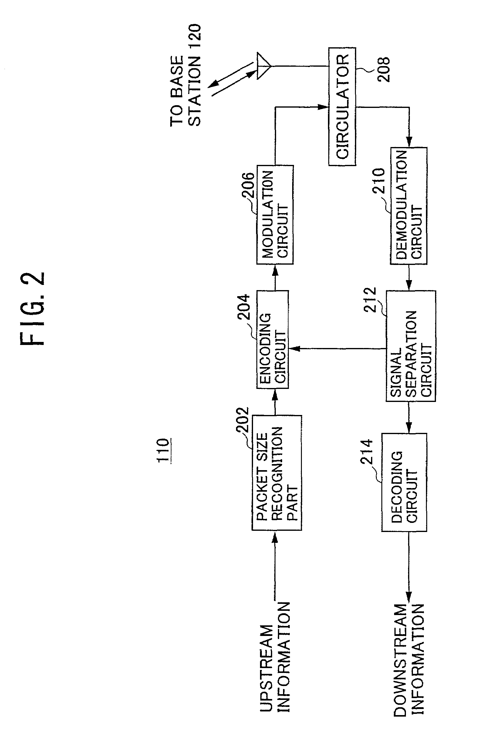
[0042]FIG. 2 illustrates an example of the structure of the mobile terminal 110 in a reservation type access system according to the present invention. As shown in FIG. 2, the mobile terminal 110 in the reservation type access system includes a packet size recognition part 202, an encoding circuit 204, a modulation circuit 206, a circulator 208, a demodulation circuit 210, a signal separation circuit 212, and a decoding circuit 214.

[0043]Additionally, FIG. 3 illustrates an example of the structure of the base station 120 in the reservation type access system according to the first embodiment of the present invention. As shown in FIG. 3, the base station 120 in the reservation type access system includes a circulator 302, a demodulation circuit 304, a signal separation circuit 306, a decoding circuit 308, a transmission rate determination circuit 310, a modulation method / radio resource determination circuit 312 (referred to as “determination circuit 312”, hereinafter), an information...

second embodiment

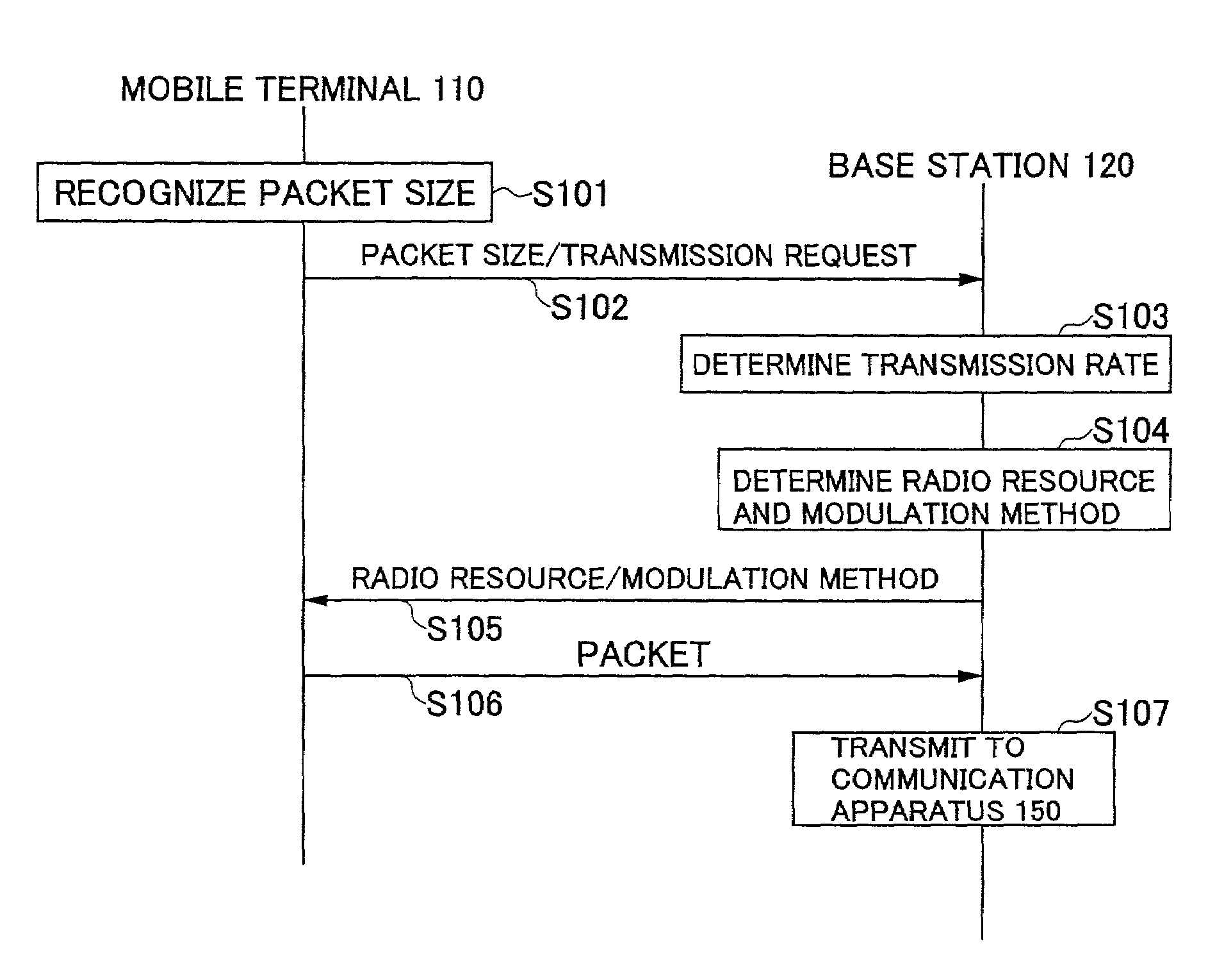
[0089]FIG. 11 is a flow diagram showing the operations of the mobile terminal 110 and the base station 120 in a case where packets are transmitted from the mobile terminal 110 to the communication apparatus 150 in the-

[0090]In step S401, the mobile terminal 110 recognizes the size of each of the packets to be transmitted. Next, in step S402, the mobile terminal 110 transmits to the base station 120 the size of the packet and a transmission request including transmission time of packet from the mobile terminal 110 that is a sender to the communication apparatus 150 that is a receiver as a transmission condition.

[0091]When the base station 120 receives the size of the packet and the transmission request from the mobile terminal 110, the base station 120 recognizes a transmission state of the upper network in step S403. In step S404, the base station 120 calculates transmission time in the wireless area. The calculation is made based on transmission time of the packet from the mobile t...


PUM


Abstract

A packet transmission method in which packets are transmitted between a base station and a mobile station communicating with the base station includes the steps of: recognizing the size of each of the packets to be transmitted; determining a transmission rate for each packet in accordance with the recognized size of the packet; allocating a radio resource to the transmission of each packet between the base station and the mobile station based on the determined transmission rate; and transmitting each packet between the base station and the mobile station using the allocated radio resource. In the method, a modulation method or a radio resource used for transmitting the packets is determined by calculating a transmission rate in a wireless area according to the size of each packet and a transmission request in the wireless area. The transmission request is recognized by the base station from an upper network when the packets are transmitted downward, while calculated by the base station based on a user request and a transmission state of the upper network when the packets are transmitted upward. Therefore, end-to-end quality of service can be provided.

Description

BACKGROUND OF THE INVENTION[0001]1. Field of the Invention[0002]The present invention relates to a packet transmission method in which packets are transmitted between a base station and a mobile station communicating with the base station when the packets are transmitted from a sender to a receiver, and to a base station and a mobile station to which the packet transmission method is applied.[0003]2. Description of the Related Art[0004]As multimedia service makes progress in these years, in addition to the conventional voice communication, non-voice communication such as image communication is being performed. In many cases, the size of each packet transmitted in the non-voice communication differs depending on an application used for processing the packet and the type of the packet (for example, types such as a control packet, an information packet, and the like). More specifically, the size of a packet varies widely from several bytes of the control packet to 1500 bytes prescribed...

Claims


Application Information

Patent Timeline
IPC IPC(8): H04Q7/20H04J3/16H04B7/216H04B7/26H04L12/801H04L12/811H04L12/911H04L29/08H04W28/00H04W28/06H04W28/22H04W72/04
CPCH04W72/08H04W28/06H04W28/22H04W72/54H04W72/04
Inventor CHEN, LANUMEDA, NARUMIYAMAO, YASUSHI
Owner NTT DOCOMO INC
Learn More