
System and method for measuring tip velocity of sprayed fuel

a technology of sprayed fuel and tip velocity, which is applied in the direction of instruments, machines/engines, devices using optical means, etc., can solve the problems of high equipment price, inability to measure the tip velocity of sprayed fuel as liquid fuel,

Inactive Publication Date: 2008-07-29
HYUNDAI MOTOR CO LTD
View PDF11 Cites 4 Cited by
  • Summary
  • Abstract
  • Description
  • Claims
  • Application Information

AI Technical Summary

Benefits of technology

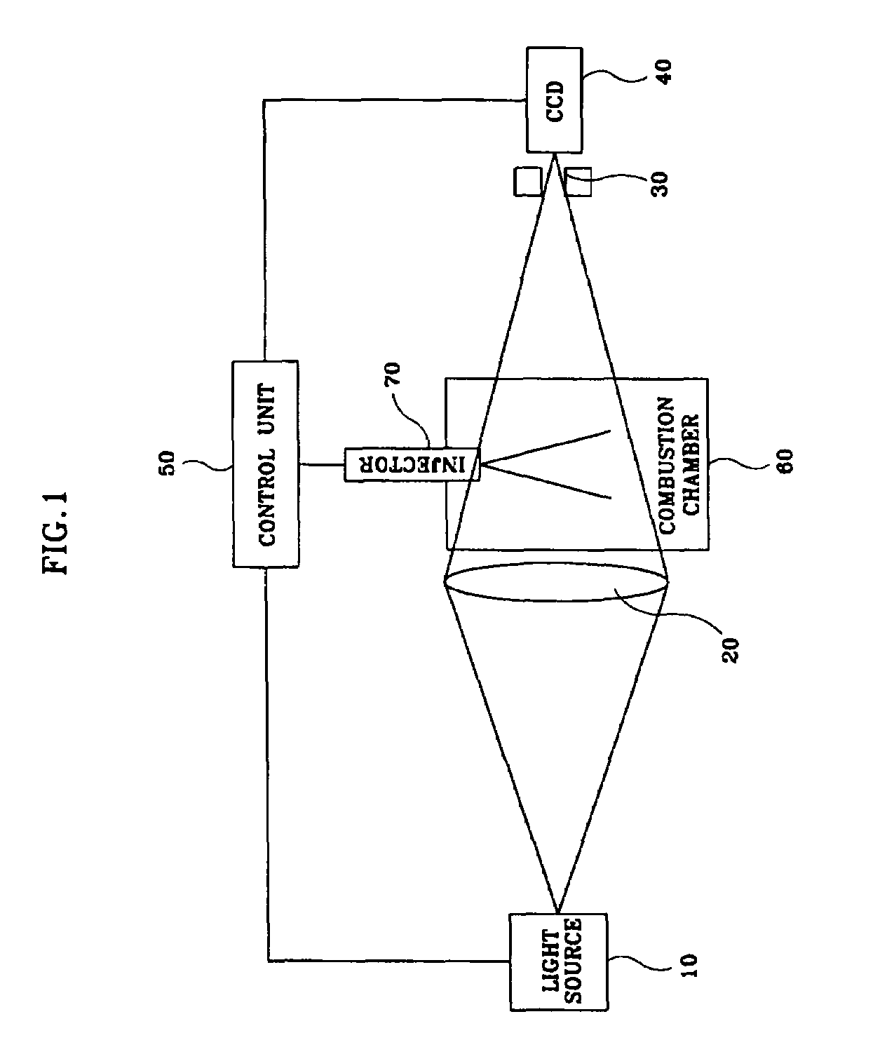
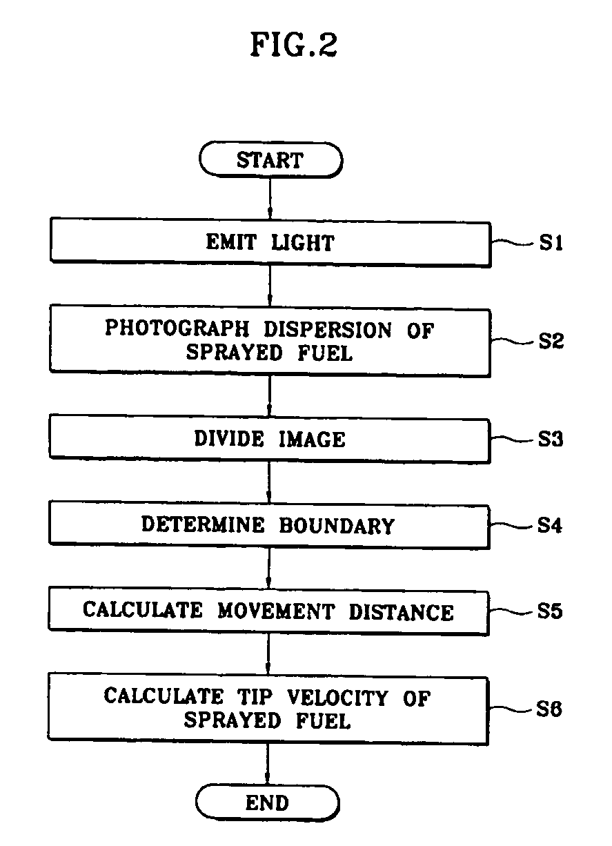
The present invention provides a system and method for measuring the tip velocity of sprayed fuel in an engine. This is achieved by photographing the shapes of the sprayed fuel while a light source emits light two times towards the fuel sprayed into a combustion chamber from an injector. The tip velocity of the sprayed fuel can be measured even when fuel is sprayed into the combustion chamber in a liquid column or liquid ligament form. The system includes a light source, a lens, a Charge-Coupled Device (CCD) camera, and a control unit. The method involves causing light to enter the combustion chamber, photographing the shapes of the sprayed fuel, dividing the image into two images based on brightness values, and calculating the tip velocity of the sprayed fuel by dividing the movement distance by the time interval in which the light source emits light two times. The technical effect of this invention is to provide a reliable and accurate method for measuring the tip velocity of sprayed fuel in an engine, which can help to improve engine performance and fuel efficiency.

Problems solved by technology

However, in the above-described methods, it is impossible to measure the velocity of sprayed fuel as liquid fuel exists in a liquid column or liquid ligament form at the early stage of fuel injection.
Furthermore, the PDA method enables real-time measurement, but uses a laser as a light source, so that equipment prices are very high.

Method used


Image

  • System and method for measuring tip velocity of sprayed fuel
  • System and method for measuring tip velocity of sprayed fuel
  • System and method for measuring tip velocity of sprayed fuel

Examples


Embodiment Construction

[0022]A preferred embodiment of the present invention is described with reference to accompanying drawings below.

[0023]As shown in FIG. 1, the system for measuring the tip velocity of sprayed fuel in an engine according to the present invention includes a light source 10, a lens 20, a pinhole 30, a CCD camera 40, and a control unit 50.

[0024]The light source 10 emits light under the control of the control unit 50, and the lens 20 is a convex lens that is located between the light source 10 and a combustion chamber 60 to condense the light emitted from the light source 10 and allow the condensed light to enter into the combustion chamber 60. That is, the distortion of an image occurs when the lens 20 is installed between the combustion chamber 60 and the CCD camera 40, so that the lens 20 is installed between the light source 10 and the combustion chamber 60 to prevent the distortion.

[0025]The pinhole 30 is located between the combustion chamber 60 and the CCD camera 40 to eliminate a...


PUM


Abstract

A system and method for measuring tip velocity of sprayed fuel in an engine includes a light source, a lens, a Charge-Coupled Device (CCD) camera, and a control unit. The lens allows light, which is emitted from the light source, to enter into a combustion chamber. The CCD camera photographs the shapes of the dispersion of the sprayed fuel. The control unit causes the light source to emit light two times by controlling the light source, acquiring a single frame image of the shapes of the dispersion of the sprayed fuel by controlling the CCD camera, and calculates the tip velocity of the sprayed fuel by processing the acquired image.

Description

CROSS-REFERENCE TO RELATED APPLICATIONS[0001]The present application is based on, and claims priority from, Korean Application Serial Number 10-2004-0079071, filed on Oct. 5, 2004, the disclosure of which is hereby incorporated by reference herein in its entirety.FIELD OF THE INVENTION[0002]The present invention relates to a system and method for measuring the tip velocity of sprayed fuel in an engine and, more particularly, to a system and method for measuring the velocity of liquid fuel sprayed from an injector into a combustion chamber in a vehicle engine.BACKGROUND OF THE INVENTION[0003]Generally, the injector of a vehicle engine supplies liquid fuel to the interior of a combination chamber. This process is accompanied by an atomization process to improve ignition performance and the combustion efficiency of fuel.[0004]The above-described atomization process of liquid fuel occurs as the pressure energy of fuel is converted into velocity energy while the liquid fuel is passed thr...

Claims


Application Information

Patent Timeline
Patent Type & Authority Patents(United States)
IPC IPC(8): G01P3/38F02B5/00
CPCG01P5/20G01P5/001G01P3/36
Inventor PARK, YOUNG-KUG
Owner HYUNDAI MOTOR CO LTD
Learn More