
Methods of forming radiation-patterning tools; carrier waves and computer readable media

a technology of radiation patterning and tooling, applied in the field of method of forming radiation patterning tools, can solve the problems of affecting the effect of a single window, affecting the quality of the printed feature, and affecting the effect of the forming of the tool,

Inactive Publication Date: 2008-07-15
MICRON TECH INC
View PDF8 Cites 2 Cited by
  • Summary
  • Abstract
  • Description
  • Claims
  • Application Information

AI Technical Summary

Problems solved by technology

However, the magnitude of the sidelobes generated from light passing through a single window is typically too small to form a printed feature.
Such can cause destructive interference which ultimately cancels a significant amount of intensity from the combined sidelobes.
This can lead to placement of a sidelobe inhibitor at the wrong location.
Also, the methodology described with reference to FIG. 10 will occasionally not recognize multiple discrete locations where sidelobe interference will occur if the locations are too close to one another.
This can result in some locations not having an appropriate sidelobe inhibitor provided.

Method used


Image

  • Methods of forming radiation-patterning tools; carrier waves and computer readable media
  • Methods of forming radiation-patterning tools; carrier waves and computer readable media
  • Methods of forming radiation-patterning tools; carrier waves and computer readable media

Examples


Embodiment Construction

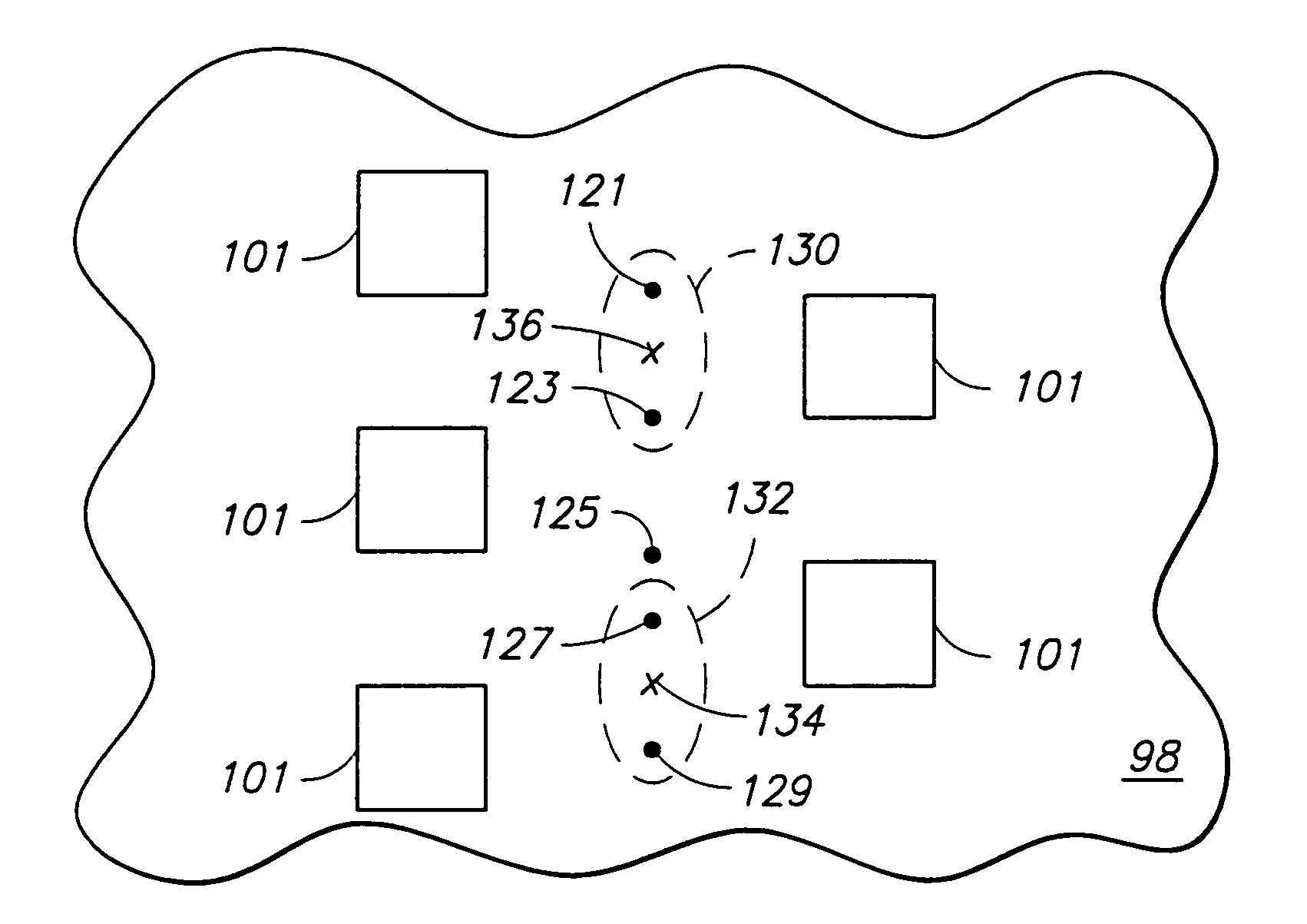
[0048]The invention includes new methodology which can be quick, efficient and accurate for determining placement of sidelobe inhibitors on radiation-patterning tools. In particular aspects, the methodology assumes that contacts will be adjacent before significant sidelobes develop. This assumption can be utilized in a heuristic routine using Design Rule Checks (DRC) in order to determine the location of the sidelobes. Methodology of the present invention can account for all of the two, three or four interaction contact scenarios of radiation-patterning tool design, and can significantly reduce the placement time of sidelobe inhibitors relative to methods which simulate light patterns passing through a radiation-patterning tool in order to determine regions of undesired sidelobe interaction. Methodology of the present invention can be used for any pitch between contacts, and can be utilized with a high degree of speed and accuracy. A method of the present invention can be utilized t...


PUM

PropertyMeasurementUnit
threshold spatial distanceaaaaaaaaaa
threshold distanceaaaaaaaaaa
threshold spatial distanceaaaaaaaaaa

Abstract

The invention includes a method for placement of sidelobe inhibitors on a radiation-patterning tool. Elements of the tool are represented by design features in a modeling domain. The modeling domain is utilized to generate vectors spanning between edges of design features within a threshold spatial distance of one another. Locations of vector midpoints are identified. The locations are utilized in identifying areas where sidelobe overlap is likely. The areas are shifted from the modeling domain to a real domain, and in the real domain correspond to regions of the tool where sidelobe overlap is likely to occur. Sidelobe inhibitors are formed across at least some of the identified regions of the tool. The invention includes computer readable code that can enable a computer to determine locations for placement of the sidelobe inhibitors.

Description

RELATED PATENT DATA[0001]This patent resulted from a continuation application of U.S. patent application Ser. No. 10 / 341,691, which was filed Jan. 13, 2003, and which is now U.S. Pat. No. 6,807,519.TECHNICAL FIELD[0002]The invention pertains to methods of forming radiation-patterning tools. In particular aspects the invention pertains to computer readable code that can enable a computer to determine locations for placement of sidelobe inhibitors. The code can be, for example, on a computer readable media or in a carrier wave.BACKGROUND OF THE INVENTION[0003]Photolithography is commonly used during formation of integrated circuits on semiconductor wafers. More specifically, a form of radiant energy (such as, for example, ultraviolet light) is passed through a radiation-patterning tool and onto a radiation-sensitive material (such as, for example, photoresist) associated with a semiconductor wafer. The radiation-patterning tool can be referred to as a photomask or a reticle. The term ...

Claims


Application Information

Patent Timeline
Patent Type & Authority Patents(United States)
IPC IPC(8): G06F17/50G03F7/20G03F1/00G03F1/36
CPCG03F1/144G03F1/36G03F7/705G03F7/70441G03F7/70433
Inventor STANTON, WILLIAM A.
Owner MICRON TECH INC
Learn More