
Electronic circuit with energy control

a technology of electronic circuits and controllers, applied in the direction of power supply for data processing, instruments, liquid/fluent solid measurement, etc., can solve the problems of large computation effort, too much to ask of any user, and inability to produce the same at low cost, so as to achieve the effect of increasing computing power

Active Publication Date: 2008-07-01
INFINEON TECH AG
View PDF12 Cites 4 Cited by
  • Summary
  • Abstract
  • Description
  • Claims
  • Application Information

AI Technical Summary

Benefits of technology

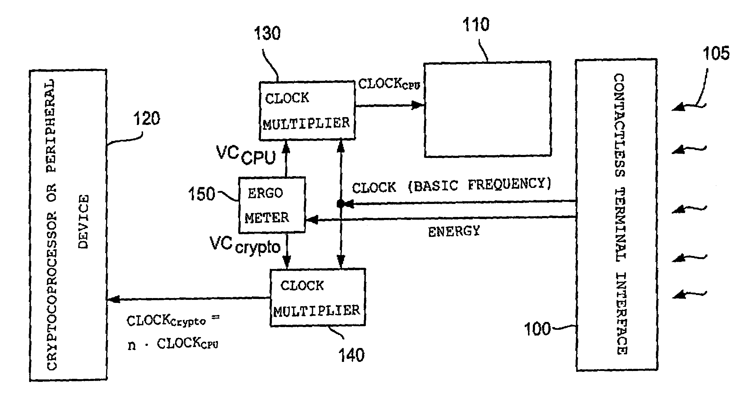
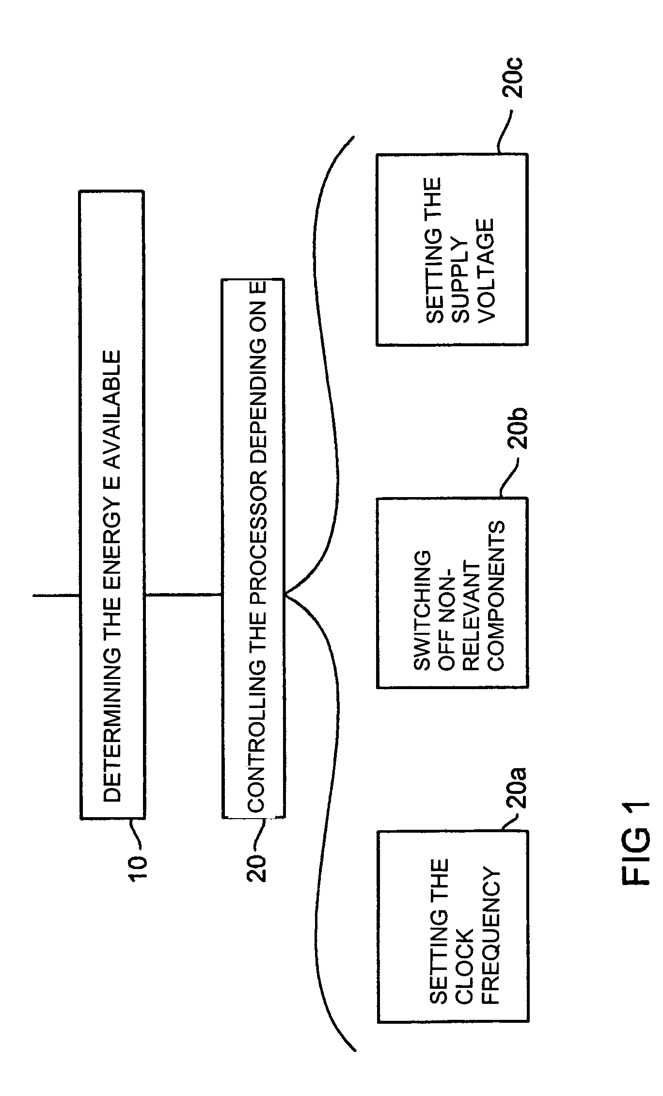
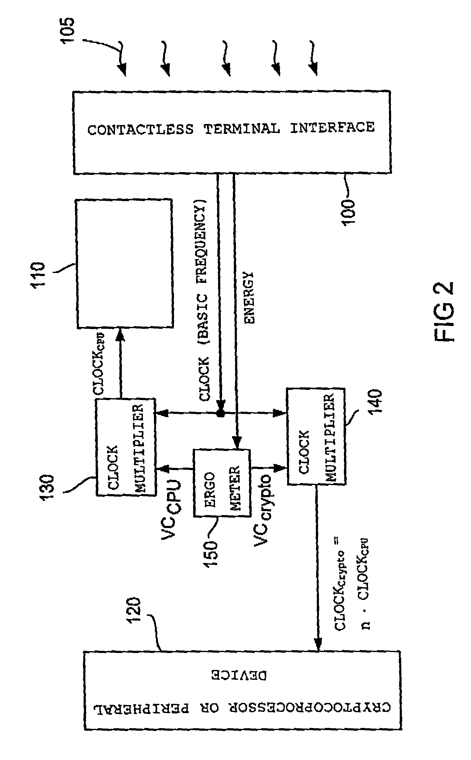
[0018]The present invention is based on the findings that by determining the energy available to the controller, such as, for example, a cryptography controller, an optimization of the computing time of an operation may be achieved in that the energy determined is distributed in an optimum manner to the decisive coprocessors, i.e., those which are primarily required for a current processor task, or other peripheral devices or the CPU of the controller. Even though an energy determination means or an ergometer is added to the electronic circuit for this purpose, whereby the complexity of same is increased, an improvement of the computing power at a constant circuit complexity, on the one hand, and a reduced circuit complexity at a constant computing power, on the other hand, may be achieved by an optimum utilization of the energy.
[0019]In accordance with one embodiment, controlling the controller is carried out as a function of the energy available to the controller in that the controller clock with which the controller is operated is increased if more energy is available, and is reduced if less energy is available. To put it another way, the controller clock is tracked in accordance with the energy determined to be available so as to achieve an optimum utilization of the energy available. This is advantageous in particular, in using the electronic circuit in chip cards provided for use in contact-less terminals since, in this case, the energy available depends on the distance between the chip card and the contact-less terminal and is, thus, subject to strong variations. In the case of a chip card, the waiting time at the terminal is reduced for the chip card owner due to the optimum energy utilization, which increases the user friendliness of the chip card.
[0021]In one embodiment, for example, the energy available is distributed among a peripheral device and a CPU of the controller for example by clocking the CPU low, or slowly, and by clocking the peripheral device, i.e., the coprocessor responsible for modular multiplications, high, or fast, due to the small amount of work to be performed by the CPU during an RSA encryption. In another embodiment, in turn, the energy available is distributed mainly among two peripheral devices by clocking high, during an elliptic-curve encryption, for example, the coprocessor mainly provided therefore, and clocking low a coprocessor required for secondary computations. In all, there is thus a reduction in the computing time required with optimum energy utilization, or exploitation.

Problems solved by technology

It would be, for example, too much to ask of any user to have to wait several minutes for an authentication check or a payment transaction.
In using cryptography controllers in chip cards, such as SIM cards or signature cards, an additional problem results from the requirement that same must be producible at low cost as a mass product.
Even though they must execute, within as short a time period as possible, algorithms requiring a large computation effort, the electronic circuit, on the other hand, must not be too complicated and, as a consequence, expensive.
A further problem in designing cryptography controllers results from the co-existence of many common cryptography algorithms.
On the grounds of multi-purpose employment, such a multi-functional cryptography controller, however, must be capable of performing a multitude of computing operations used by many cryptographic algorithms, which leads to an increase in the complexity or a decrease in the speed of the electronic circuit.
An additional problem that cryptography controllers must face is that only a limited energy is available to them.
Consequently, the computing speed of the coprocessors is limited by the energy available.
The clock frequency with which the CPU and the cryptocoprocessors are clocked is subject to limitations imposed by the energy available, since in the implementation of the controller chip in CMOS technology, the current consumption depends on the clock frequency or on the switching frequency of the MOSFETs.
The problems associated with the low energy available and, in contact-less and mobile applications, even varying or decreasing amounts of energy available are dealt with, in conventional cryptography controllers, only in that same are designed for a certain minimum energy supply.
In the event that the energy available exceeds the energy required for operating the cryptography controller, the additional energy available is lost and remains unused.

Method used


Image

  • Electronic circuit with energy control
  • Electronic circuit with energy control
  • Electronic circuit with energy control

Examples


Embodiment Construction

[0028]Firstly, the inventive energy control and the advantages resulting from it will be described with reference to FIG. 1. With reference to FIGS. 2 and 3, an embodiment of an electronic circuit in accordance with the present invention will then be described. With reference to FIG. 4, the application of the inventive energy control will finally be illustrated in the case of contact-less applications.

[0029]Even though the present invention may be applied to all electronic circuits comprising a controller for processing a processor task, the following description particularly relates to the field of cryptography, the controller in the following sometimes being referred to as cryptography processor or cryptography controller. However, a transfer of the following description to other fields, such as graphic cards in a laptop, is readily possible.

[0030]As is shown in the flow chart of FIG. 1, the inventive energy control starts in a step 10 with determining the energy E available to th...


PUM


Abstract

An inventive electronic circuit includes a controller for processing a processor task as well as an energy determination means for determining the energy available to the controller. A control means of the electronic circuit controls the controller depending on the energy available to the controller. An optimum utilization of the energy available and, thus, an optimization of the computing speed with maximum energy utilization is achieved by means of the energy control.

Description

[0001]This application is a Continuation of International Patent Application Ser. No. PCT / EP02 / 06233, filed Jun. 6, 2002, which published in German on Dec. 12, 2002 as WO 02 / 099,554 A2.BACKGROUND OF THE INVENTION[0002]1. Field of the Invention[0003]The present invention relates to electronic circuits with a controller and, in particular, to controlling the controller in these electronic circuits.[0004]2. Description of the Prior Art[0005]With the increasingly widespread use of cashless payment transactions, electronic data transmission via public networks, and the exchange of credit card numbers via public networks, there is an increasing need for cryptography algorithms so as to be able to implement digital signatures, authentications or encryption tasks. Known cryptography algorithms include asymmetrical encryption algorithms, such as the RSA algorithm, or methods based on elliptic curves, or symmetrical encryption methods, such as encryption methods in accordance with the DES or ...

Claims


Application Information

Patent Timeline
Patent Type & Authority Patents(United States)
IPC IPC(8): G06F1/26G06F1/32G06F5/00G06K19/07
CPCG06K19/0723G06K19/0701G06F1/26
Inventor ELBE, ASTRIDJANSSEN, NORBERTSEDLAK, HOLGER
Owner INFINEON TECH AG
Learn More