Oxide superconductor current lead and method of manufacturing the same, and superconducting system

Inactive Publication Date: 2008-07-01
DOWA ELECTRONICS MATERIALS CO LTD +1
View PDF13 Cites 8 Cited by
  • Summary
  • Abstract
  • Description
  • Claims
  • Application Information

AI Technical Summary

Benefits of technology

[0050]As a result, it was found out that there were the holes in the joining metal on the joint surfaces of the oxide superconductor and the metallic electrodes. It was also found out that when the volumes of the holes in the joining metal were totaled, the volume of the holes substantially constitutes 30% or more of the volumetric capacity of the joint portions. Thus, when the volume of the holes in the joining metal was made 5% or less of the volumetric capacity of the joint portions, the contact resistance values of the oxide superconductor and the metallic electrodes were reduced, and it became possible to join the oxide superconductor to the metallic electrodes without enlarging the sectional area of the oxide superconductor in the contact portions of the oxide superconductor and the metallic electrodes, and to restrain generating Joule heat even if a predetermined current was passed.
[0061]In the twelfth constitution, since the superconducting system using the oxide superconductor current lead according to any one of the seventh to the eleventh constitution has less heat penetration from the high temperature side to the low temperature side even when a predetermined current is passed, the load on the cryocooler can be reduced, and the superconducting system at the low production cost and the running cost is provided.

Problems solved by technology

As a result, power loss of a cryocooler and loss of a He gas as a refrigerant due to the heat penetration become serious.
The heat generation occurs because the oxide superconductor used for the oxide superconductor current lead is made of ceramics and has unfavorable joinability with metal, and thus the electric resistance (hereinafter, described as contact resistance) which cannot be ignored occurs to joint surfaces with the metallic electrodes (generally, a copper electrodes are used).
However, as a result that a current passed through the current lead increases, generating Joule heat is not be ignorable with the current lead using the aforementioned oxide superconductor with the silver coat.
However, in the rare-earth based oxide superconductor produced by the melting method, which is suitable for the current lead among the oxide superconductors, it is difficult to produce a molded body with only a central portion being constricted to be slim as shown in FIG. 6.
However, with this method, when a predetermined current value passed through the oxide superconductor current lead is large, a large-sized rare-earth based oxide superconductor is produced, and the large-sized rare-earth based oxide superconductor has to be cut large, thus reducing yields of the rare-earth based oxide superconductor and requiring a large number of man-hours.
Further, the portions of the metallic electrodes are upsized, and therefore it is difficult to reduce the size of the entire oxide superconductor current lead.
However, the problem that the reduction effect of the contact resistance value remains small even if the aforesaid joint area is only made large.
However, if the methods of heating the joint portions, such as welding and brazing are adopted for improvement in joining, thermal load is applied to the oxide superconductor in the current lead, as a result of which, the phenomenon that the oxide superconductor becomes rid of oxygen occurs, and the characteristics of the oxide superconductor are sometimes deteriorated.
Further, even if the joint portions are welded or the like, variations in the contact resistance value in the joint interface of both of them cannot be restrained completely, and when a large current is passed, a drift current occurs to cause an increase in the contact resistance value.

Method used


Image

  • Oxide superconductor current lead and method of manufacturing the same, and superconducting system
  • Oxide superconductor current lead and method of manufacturing the same, and superconducting system
  • Oxide superconductor current lead and method of manufacturing the same, and superconducting system

Examples


first embodiment

[0080]The first embodiment of the present invention will be explained with reference to the drawings hereinafter.

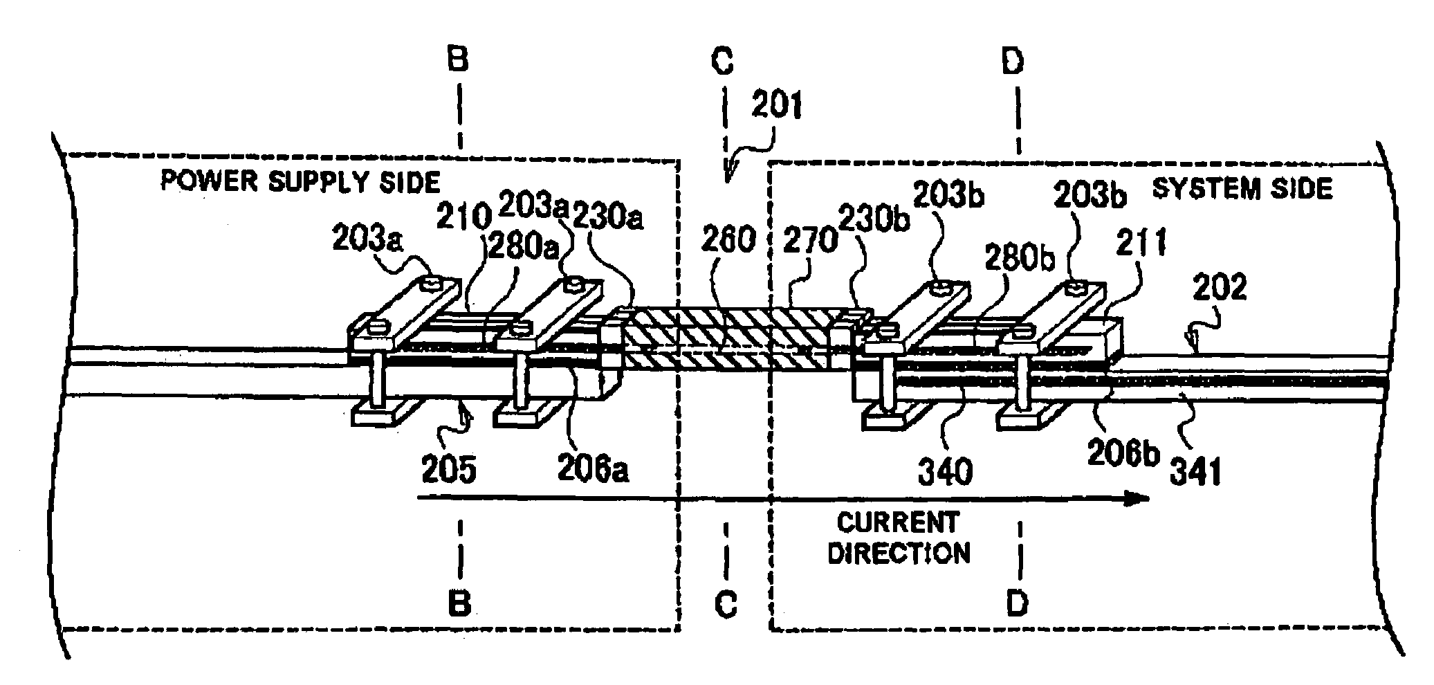
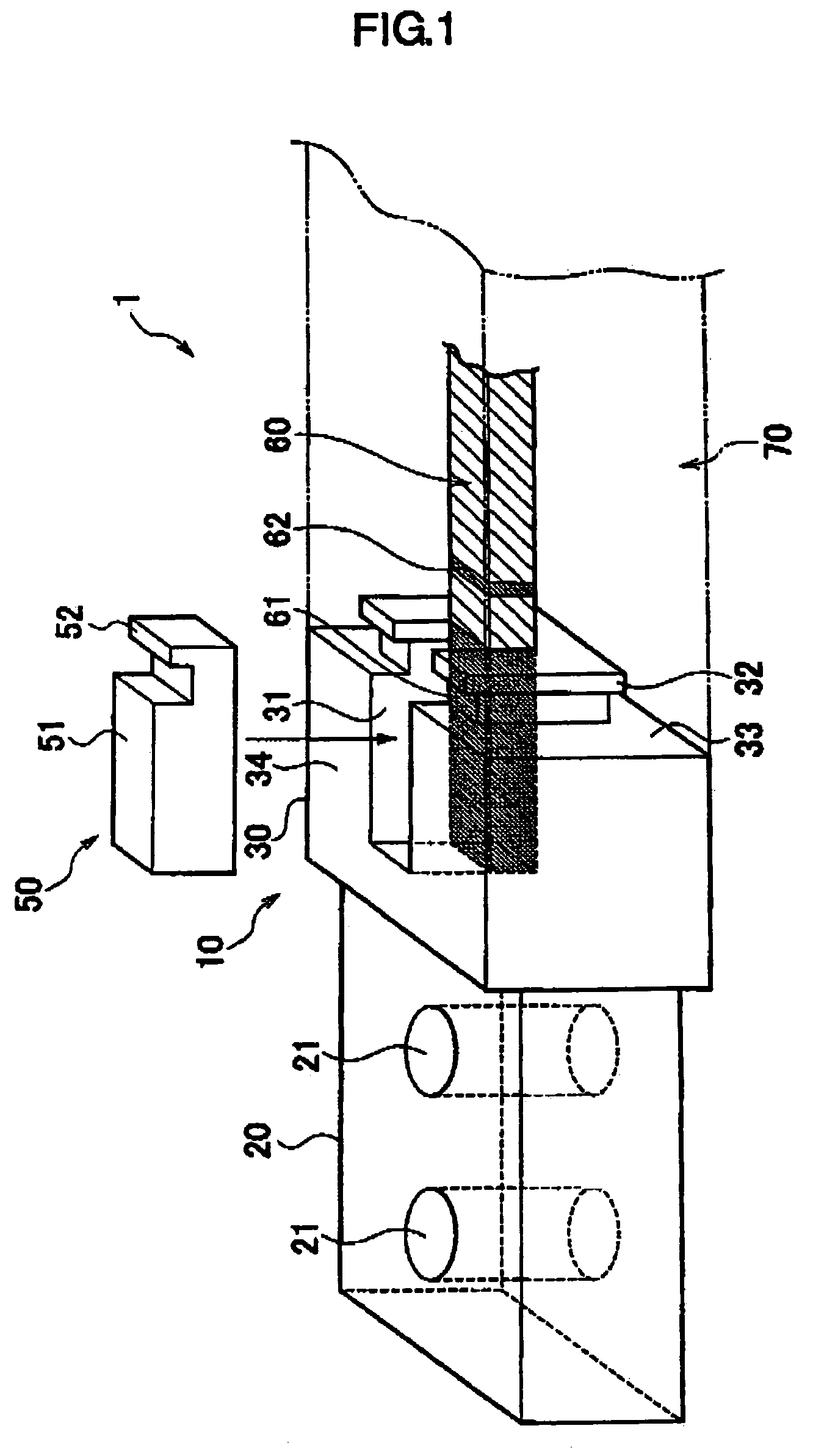
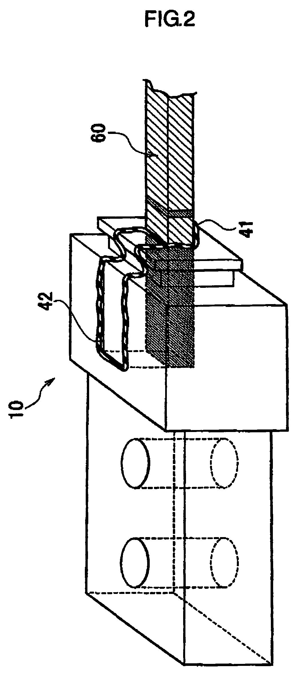
[0081]FIG. 1 is a perspective view showing a placement example of an oxide superconductor to a metallic electrode in an oxide superconductor current lead according to the present invention, FIG. 2 is a perspective view in a case in which a sealing member is provided at the metallic electrode in which the oxide superconductor shown in FIG. 1 is placed, FIG. 3 is a conceptual diagram of measurement of characteristics of an oxide superconductor current lead according to the present invention, FIG. 4 is a perspective view when the aforesaid joined body is housed in a mold to coat the joined body of the oxide superconductor and the metallic electrodes with a coating member, and FIG. 5 is a schematic cross sectional view of a joint portion of the oxide superconductor and the metallic electrode in an oxide superconductor current lead made by a prior art.

[0082]In FIG. 1, an oxide...

example 3

[0176]1) Production of the Columnar Oxide Superconductor

[0177]Each raw material powder of Sm2O3, BaCO3, and CuO was weighed so that Sm:Ba:Cu=1:2:3 in the mole ratio and mixed, then calcined at 920° C. for 30 hours, thereafter ground into the average grain size of 3 μm with use of the pot mill, and calcined again at 930° C. for 30 hours and ground into the average grain size of 10 μm in the mixing and grinding machine, and the pot mill, whereby the powder of Sm1Ba2Cu3O7−x that was the first calcined powder was prepared.

[0178]Next, the aforesaid each raw material powder was weighed so that Sm:Ba:Cu=2:1:1 and mixed, then calcined at 890° C. for 20 hours, and ground into the average grain size of 0.7 μm with use of the pot mill, whereby the powder of Sm2BaCuO5, which was the second calcined powder, was prepared.

[0179]The first and the second calcined powders were weighed so that Sm1Ba2Cu3O7−x Sm2BaCuO5=1:0.4, and Pt powder (average grain size 0.01 μm) and Ag2O powder (average grain size...

example 4

[0201]The oxide superconductor current lead sample was produced similarly to the example 1 except for that the temperature of 6) the degassing treatment of the joining metal in the example 1 was set at 160° C.

[0202]When the contact resistance values of the joint portions of the metallic electrodes and the oxide superconductor at the both sides of the current lead sample were calculated as in the example 1, it was revealed that the one was 0.3 μΩ, and the other was 0.27 μΩ, which were very low values.

[0203]When the current lead sample was further cooled to 4.2 K, and the contact resistance values between the metallic electrodes and the oxide superconductor were calculated, it was revealed that the contact resistance values at the both sides were 0.05 μΩ, which was a very low value.

[0204]Meanwhile, the critical current value and the penetrating heat at 77 K in the magnetic field of 0.5 T were substantially at the same levels as in the example 1.

[0205]From the above, it was revealed th...


PUM

PropertyMeasurementUnit
Fractionaaaaaaaaaa
Electrical resistanceaaaaaaaaaa
Currentaaaaaaaaaa

Abstract

An oxide superconductor current lead in which generation of Joule heat at joint portions with a system side conductor and a power supply side conductor is reduced with use of an oxide superconductor with less heat penetration into a super conducting equipment system is provided. A columnar oxide superconductor molten bodies (interelectrode superconductor 260, in-electrode superconductors 280a and 280b) are produced, the in-electrode superconductor 280a and a left end portion of the interelectrode superconductor 260 are placed into a power supply side metallic electrode 210, and the in-electrode superconductor 280b and a right end portion of the interelectrode superconductor 260 are similarly placed in a system side metallic electrode 211, then degassed joining metal is used to join them to form an oxide superconductor current lead 201, a power supply side conductor 5 from a power supply is joined to the power supply side metallic electrode 210, and a system side conductor 202 from a superconducting system side is joined to the system side metallic electrode 211 with use of respective clamps 203a and 203b.

Description

BACKGROUND OF THE INVENTION[0001]1. Field of the Invention[0002]The present invention relates to an oxide superconductor current lead to be used when supplying a current to a superconducting system used in an MRI, linear, SMES and the like, and to a method of manufacturing the same, and a superconducting system.[0003]2. Description of the Related Art[0004]A current lead, which is used when a large current is supplied to superconducting equipment such as a superconducting magnet, is for supplying a current of several hundreds to several thousands amperes to a cryogenic superconducting system from a power supply in a room temperature region. As the current lead, a copper wire with a low electrical resistance value is conventionally used. However, when the copper wire is used as a current lead, and a predetermined large current is passed through this, Joule heat is generated. Then, when a copper wire with a large wire diameter is used to reduce generation of Joule heat, heat penetratio...

Claims


Application Information

Patent Timeline
IPC IPC(8): H01B12/00H01R4/68
CPCH01R4/68Y10T29/49014
Inventor KOHAYASHI, SHUICHIUEMURA, KAZUYUKINAGAYA, SHIGEOKASHIMA, NAOJI
Owner DOWA ELECTRONICS MATERIALS CO LTD
Why Eureka
Try Eureka