
Changing of operating voltage in semiconductor integrated circuit

a technology of operating voltage and integrated circuit, which is applied in the direction of liquid/fluent solid measurement, instruments, sustainable buildings, etc., can solve the problems of major leak current presence, significant proportion that cannot be ignored, and increase in leak currents

Inactive Publication Date: 2008-06-24
SOCIONEXT INC
View PDF11 Cites 36 Cited by
  • Summary
  • Abstract
  • Description
  • Claims
  • Application Information

AI Technical Summary

Benefits of technology

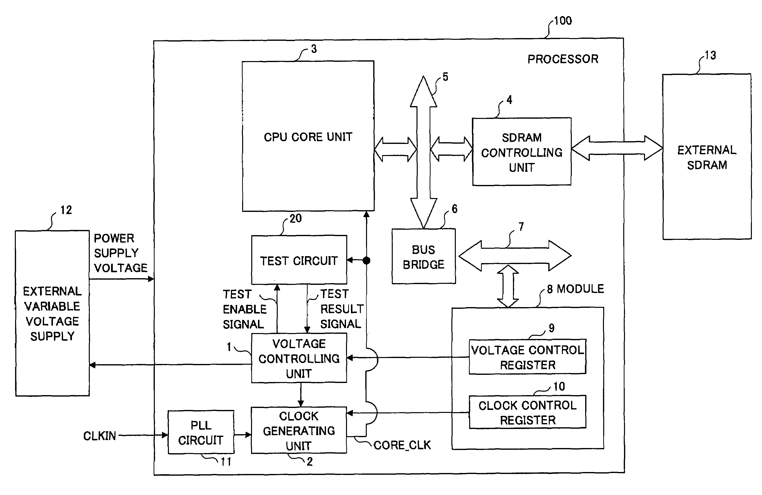
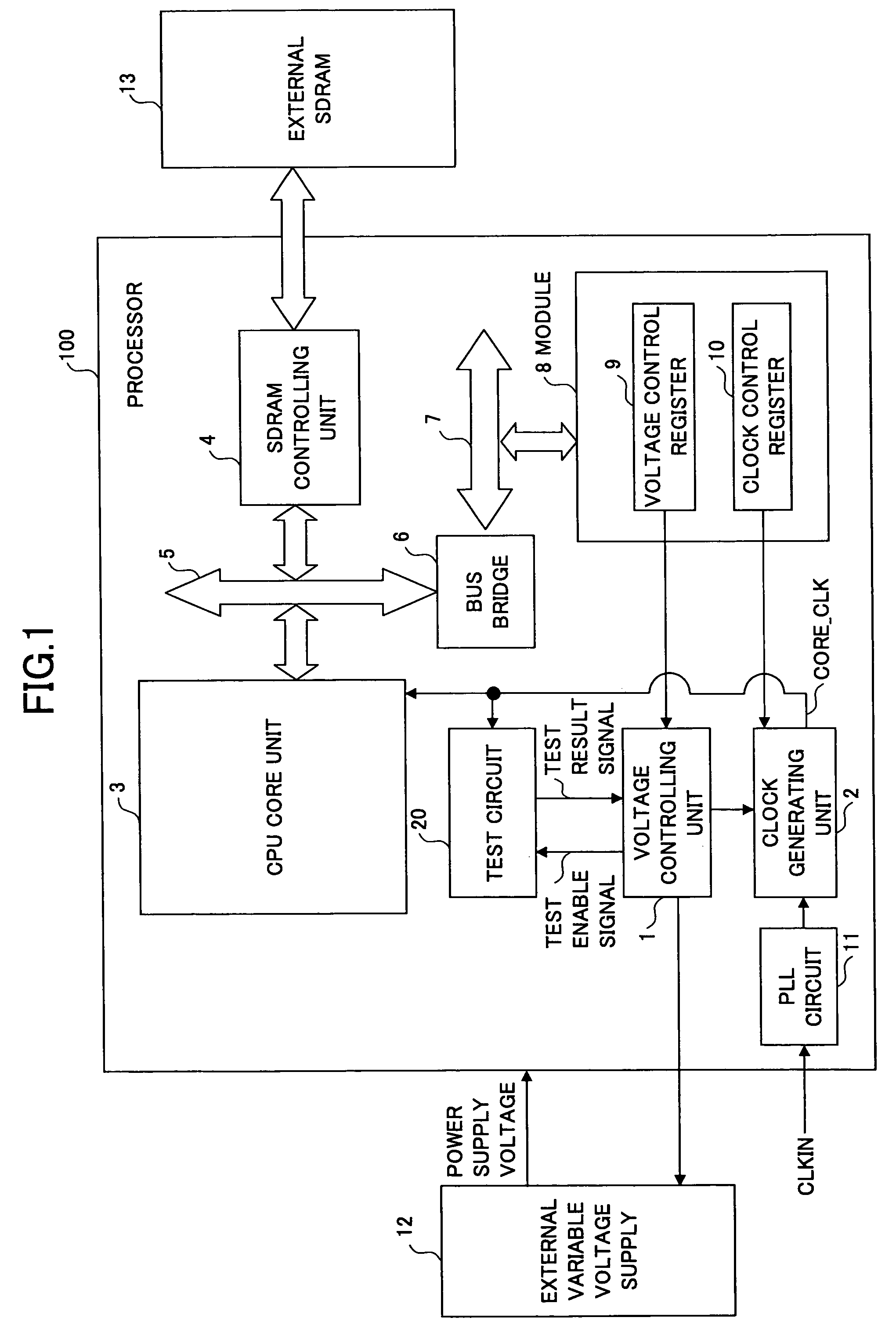
The present invention provides a semiconductor integrated circuit that can overcome the limitations and disadvantages of related art. The invention includes a module, a voltage controlling unit, a clock generating unit, and a test circuit. The test circuit can emulate a delay of a critical path to test whether the module operates properly at a new power supply voltage. The invention also includes a monitor circuit to detect a hangup of the core circuit and reset it for better performance. The invention can select an optimum voltage level based on chip-specific and environment-specific operating characteristics to prevent malfunctions when changing the operating voltage of the module dynamically. The core circuit can recover to normal operating conditions even if it suffers a hangup for some reason.

Problems solved by technology

In such a case, leak currents that are conventionally regarded as errors account for a significant proportion that can no longer be ignored.
Further, an increase in chip temperature responsive to the rise of the operating voltage also results in an increase in the leak currents.
Because of this, the presence of leak currents is a major issue that needs to be addressed to achieve low power consumption.
If the voltage goes down below this lower voltage limit, the delay of semiconductor devices making up the processor increases, thereby presenting a risk of the processor failing to properly perform the execution of instructions and thus suffering a hangup.
Decreasing the internal voltage, on the other hand, presents a risk of the processor failing to perform the execution of instructions and suffering a hangup.
Semiconductor integrated circuits may have the performance thereof deteriorating due to factors such as a temperature increase even during an ongoing operation.
A voltage range that is identified under certain operating conditions as permitting proper operation may no longer allow proper operation after a change in the operating conditions.

Method used


Image

  • Changing of operating voltage in semiconductor integrated circuit
  • Changing of operating voltage in semiconductor integrated circuit
  • Changing of operating voltage in semiconductor integrated circuit

Examples


second embodiment

[0058]FIG. 5 is a drawing showing an example of the construction of the processor 100. In FIG. 5, the same elements as those of FIG. 1 are referred to by the same numerals, and a description thereof will be omitted.

[0059]In FIG. 5, a performance monitoring circuit 30 is provided in place of the test circuit 20 of FIG. 1. Further, the module 8 is provided with a test control register 32 for storing settings for control of the operation of the performance monitoring circuit 30 and a performance monitor register 33 for storing monitor results obtained by the performance monitoring circuit 30. These registers are accessible through buses by the CPU core unit 3, and are controlled and read according to program instructions executed by the CPU core unit 3.

[0060]The performance monitoring circuit 30 includes a counter 31 and a plurality of test circuits 20-1 through 20-3 (three in an illustrated example). Each of the test circuits 20-1 through 20-3 may have the same configuration as the te...

first embodiment

[0063]The plurality of test result signals indicative of these results are supplied to the voltage controlling unit 1, thereby achieving more diligent voltage control compared to the embodiment shown in FIG. 1. Alternatively, only one of the plurality of test result signals may be supplied to the voltage controlling unit 1. In this case, the same voltage control operation as that of the first embodiment shown in FIG. 1 is carried out.

[0064]In the present embodiment, further, test results obtained with respect to a plurality of delay lengths are periodically stored in the performance monitor register 33 as monitor results, which are then referred to by a program such as an OS executed by the CPU core unit 3 as such need arises. With this provision, a check as to whether an operating environment is deteriorating is made at appropriate timing (e.g., at constant intervals) by a monitoring operation based on software such as an OS executed by the CPU core unit 3. This check is made even ...

third embodiment

[0069]FIG. 7 is a block diagram showing an example of the construction of the processor 100. In FIG. 7, the same elements as those of FIG. 5 are referred to by the same numerals, and a description thereof will be omitted.

[0070]The processor 100 of FIG. 7 includes an interruption controlling unit 40 in addition to the construction of FIG. 5. Moreover, the module 8 is provided with an interruption generation register 34 for the control of interruption operation of the interruption controlling unit 40. A battery error signal generated by the external variable voltage supply 12 is supplied to the voltage controlling unit 1. The voltage controlling unit 1 checks an operating condition based on the battery error signal supplied from the external variable voltage supply 12 or monitor results supplied from the performance monitoring circuit 30. Upon finding that the operating condition is unsafe, the voltage controlling unit 1 may assert an interruption directly to the CPU core unit 3, or m...


PUM


Abstract

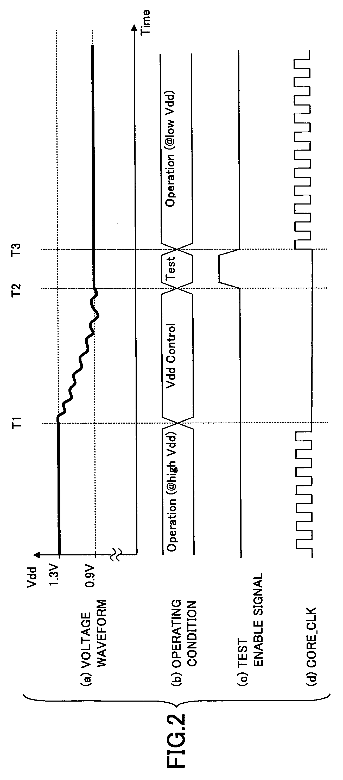
A semiconductor integrated circuit includes a module configured to operate based on a clock signal, a voltage controlling unit configured to change a power supply voltage supplied to the module, a clock generating unit configured to supply the clock signal to the module, and a test circuit configured to operate at the power supply voltage based on the clock signal to emulate a delay of a critical path provided in the module, thereby testing whether the module properly operates at the power supply voltage, wherein the clock generating unit supplies a different signal, in place of the clock signal, to the module while the voltage controlling unit is changing the power supply voltage.

Description

CROSS-REFERENCE TO RELATED APPLICATIONS[0001]The present application is based upon and claims the benefit of priority from the prior Japanese Patent Application No. 2004-182467 filed on Jun. 21, 2004, with the Japanese Patent Office, the entire contents of which are incorporated herein by reference.BACKGROUND OF THE INVENTION[0002]1. Field of the Invention[0003]The present invention generally relates to semiconductor integrated circuits, and particularly relates to a semiconductor integrated circuit in which an internal operating voltage is changed.[0004]2. Description of the Related Art[0005]In order to reduce the power consumption of semiconductor integrated circuits, voltage levels are generally optimized. With the development of the semiconductor process technology, processors or the like are now manufactured with a technology that achieves fine patterns such as 0.13 micrometers or less. In such a case, leak currents that are conventionally regarded as errors account for a signi...

Claims


Application Information

Patent Timeline
Patent Type & Authority Patents(United States)
IPC IPC(8): G06F1/32G06F9/00
CPCG06F1/3203G06F1/3296Y02B60/1285Y02D10/00
Inventor SHIKATA, TAKASHI
Owner SOCIONEXT INC
Learn More