Automated priming station

Inactive Publication Date: 2008-06-24
DESIGNETICS
View PDF27 Cites 5 Cited by
  • Summary
  • Abstract
  • Description
  • Claims
  • Application Information

AI Technical Summary

Benefits of technology

[0012]A family of interchangeable applicator tips is provided for use with a dispenser adapted to provide an on-demand supply of primer compound to the tip in use. The different applicator tips of the family have configurations particularly adapted to applying bands of primer compound along selected peripheral margins of a sheet member, and each is of composite construction including a relatively rigid base member to which is bonded a soft wicking and absorbent body for contacting and transferring to the sheet surface the layer of primer compound. The tips are readily attachable to and removable from a fluid dispenser or other dispensing unit providing a supply of the primer compound. The fluid dispenser, or a plurality of the fluid dispensers, may be incorporated in a modular work station including a closed storage and supply container for the primer compound and a solvent flush system for cleaning hoses and fluid dispenser of the reaction priming resins. The fluid dispenser may also be mounted upon an oscillating carriage whereby in one position of the carriage, spent applicator tips are removed and replaced by new tips by a loader, and in another position the marginal edges of glazing units are moved through the applicator tips by a robot arm for application of a band of the priming compound.
[0015]The design and the unique operational programmable functions, provide precision liquid lay down on glass and other products in a controlled and rapid automatic production cycle. This design with the employment of two fluid applicators on separate indexing arms provides many advantages such as:
[0017]2. The ability to use the same liquid within both fluid dispensers, but employ different applicator tips to give variable lay down;
[0025]Another object of the invention is to provide such a device which minimizes waste of the primer or adhesion promoting material.
[0029]Yet another object of the invention is to provide such a device utilizing a closed supply system so as to minimize escape of solvent materials at the work station and entry of moisture to sensitive reactive fluids.

Problems solved by technology

Assembly and installation of such units was relatively slow and costly inasmuch as a considerable amount of labor was required.
The procedure was not readily adaptable to being speeded up to accommodate increased automobile production line rates, nor was it adapted to being automated.
However, due to the labor required in manually assembling the frame and gasket on the sheet of glass, the structures are relatively costly.
Due to the nature of the glass surfaces, it is known that the gasket materials may not form a permanent, long term bond directly to the glass.
Thus, they may not maintain adhesion to the glass surface for a length of time consistent with the life of the automobile.
Exposure to weather moisture and sunlight, as well as other factors, may cause the gasket material to loosen from the glass with the passage of time, and ultimately to separate entirely from the glass.
In any event, the procedures are not entirely satisfactory in that they are time-consuming, labor-intensive and may not result in a satisfactory coating of the primer material.
Should the layer be of excessive thickness, it may separate within the layer along a cleavage plane, resulting in failure of the bond.
Of course, if the layer is not of sufficient thickness or if certain areas are not coated, the primer layer would likewise be ineffective for its intended purpose.
The primer, and particularly the solvent therefore, may be toxic in nature so that manual application thereof, particularly when using an open container of the primer, may require use of protective equipment by the workers.
Such manual application processes also generally result in waste of the primer material and generally messy conditions in the work place.
Due to the difficulty in controlling the width of manually applied bands, it may also be necessary to mask the work piece prior to application of the primer material.
Thus, as will be readily apparent, the existing procedures for applying primer material to the edges of sheet material are not entirely satisfactory, and there is a need for a system for efficiently applying a band of primer of a desired uniform thickness and width to such sheet material.

Method used


Image

  • Automated priming station
  • Automated priming station
  • Automated priming station

Examples


Embodiment Construction

[0064]The invention is directed to an automated system for applying a fluid to an object. The automated system utilizes a compliance mechanism that enhances the ability of the automated system to retain contact with the object. The automated system is easily interfaced with robots or other automated devices such as programmable fluid dispensing systems. The features of the invention will be more readily understood by referring to the attached drawings in combination with the following description of the invention.

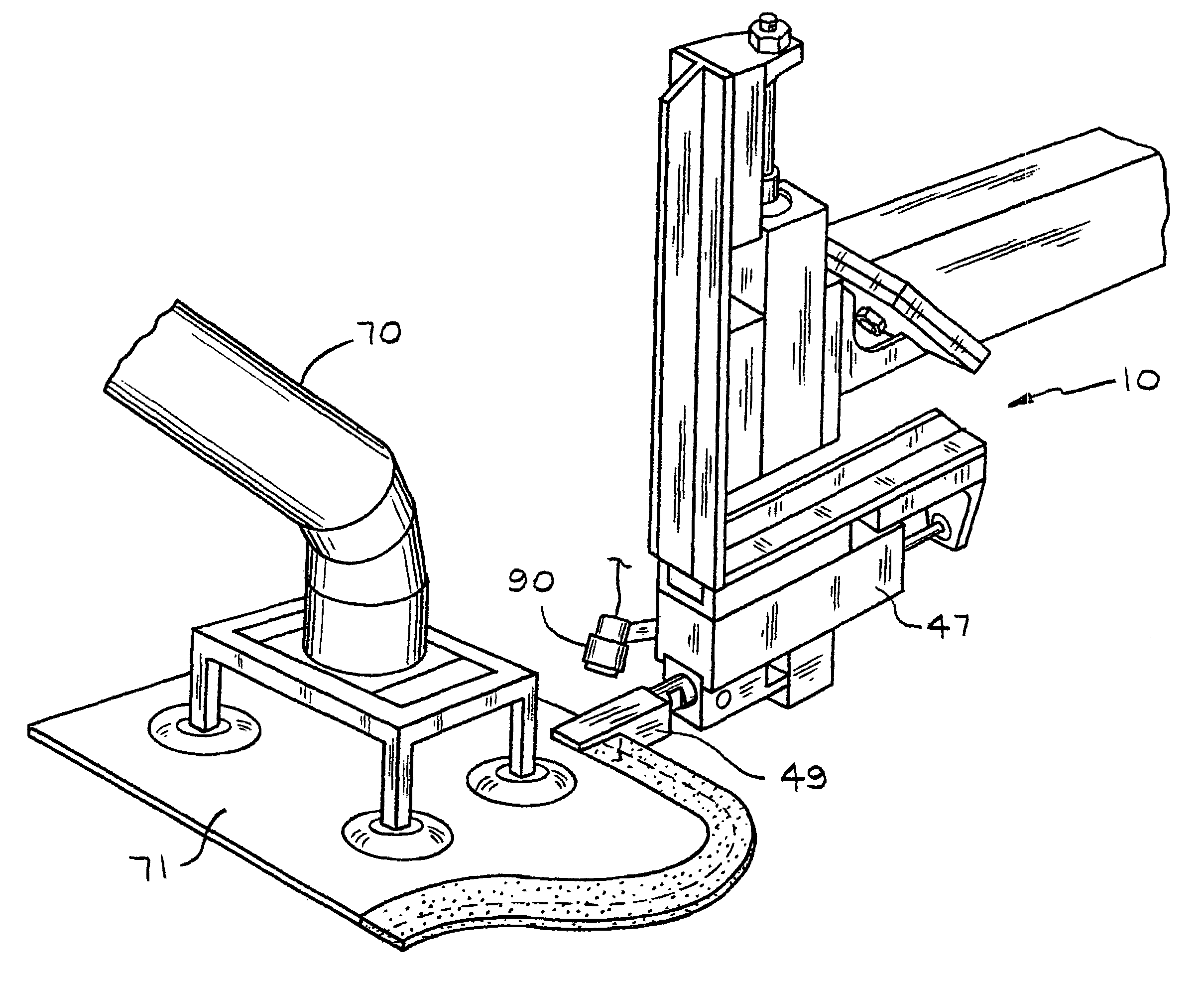
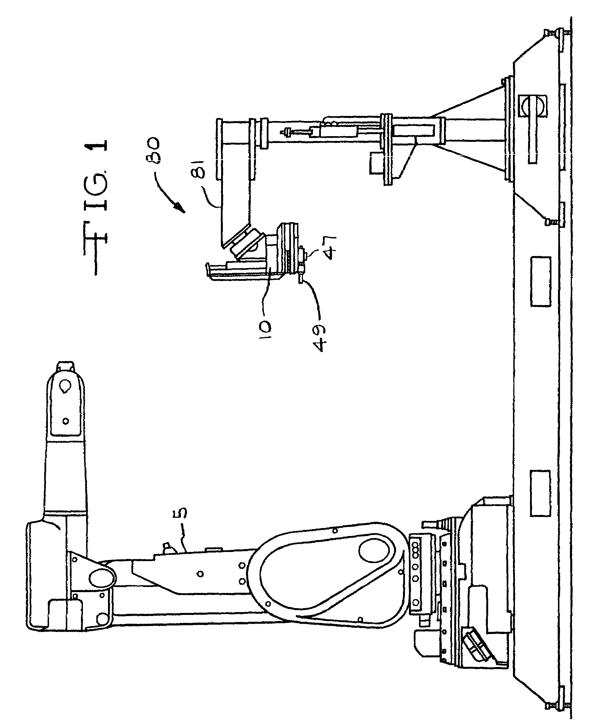
[0065]FIG. 1 shows the automated system 80 of the present invention where a fluid dispenser 47 having an applicator tip 49 is used to apply a fluid to an object (not shown). A compliance mechanism 10 is utilized to assist in maintaining the applicator tip 49 of the fluid dispenser 47 in contact with the object during the coating operation. A robot 5 having an arm 13 is utilized to advance the object past the applicator tip 49 during the coating operation. The fluid dispense...


PUM

PropertyMeasurementUnit
Diameteraaaaaaaaaa
Flexibilityaaaaaaaaaa

Abstract

The automated system includes a fluid dispenser having an applicator tip which is used to apply a fluid to an object. A compliance mechanism is utilized to assist in maintaining the applicator tip of the fluid dispenser in contact with the object during the coating operation. A robot can be utilized to advance the object past the applicator tip during the coating operation. The fluid dispenser is mounted on a movable arm to allow the fluid dispenser to be moved or rotated into and away from the position where fluid is applied to the object. The automated system provides a fluid application system that can apply a precise and repeatable layer of fluid to an object. The use of the robot allows larger objects to be easily handled and for the coating process to be done in a rapid fashion. The automated system is flexible and can readily accommodate changes in the object that is to be coated or the configuration of the coating that is to be applied to the object.

Description

RELATED APPLICATION[0001]This is a division of U.S. application Ser. No. 10 / 236,679, filed Sep. 6, 2002 now U.S. Pat. No. 6,641,665, which is a division of U.S. application Ser. No. 09 / 565,908, filed May 5, 2000 which is now U.S. Pat. No. 6,471,774 which was granted on Oct. 29, 2002.FIELD OF THE INVENTION[0002]The invention is directed to an automated system for applying a fluid to an object. The automated system is used to position a fluid applicator in the proper position with respect to the object on which the fluid is being applied. The automated system also has a mechanism for replacing worn fluid applicator tips on the fluid applicator. The automated system utilizes a compliance mechanism that enhances the ability of the automated system to retain contact with the object. The automated system is easily interfaced with robots or other automated devices such as programmable fluid dispensing systems.[0003]One of the primary applications of the automated system is the automotive g...

Claims


Application Information

Patent Timeline
IPC IPC(8): B05D5/06B05B9/04B05C1/06B05C5/02B05C11/10B05C13/02C03C17/00
CPCB05C1/06B05C5/0204B05C5/0216B05C11/10C03C17/002B05B15/02B05C5/022B05B9/04B05C13/02B05C11/101B05C11/1023B05B15/50
Inventor KRUEGER, WALLACE F.
Owner DESIGNETICS
Why Eureka
Try Eureka