
System and method for exposure of partial edge die

a technology of partial edge die and system, applied in the field of semiconductor devices, can solve the problems of reducing the adherence of features to the wafer surface, affecting the sensitivity of the rounded edge of the wafer, so as to reduce the disadvantages and problems of the rounded edge, and achieve the effect of reducing the disadvantages and problems

Active Publication Date: 2008-05-20
TEXAS INSTR INC
View PDF5 Cites 2 Cited by
  • Summary
  • Abstract
  • Description
  • Claims
  • Application Information

AI Technical Summary

Benefits of technology

The present invention provides a system and method for forming semiconductor devices on the surface of a wafer that addresses the problems and disadvantages associated with conventional semiconductor fabrication equipment. The method includes assigning exposure intensities to different areas of the wafer based on their location, which allows for varying energy usage to reduce pattern deformities and improve adherence of features to the wafer. This also reduces the occurrence of detached features and contamination during subsequent fabrication processes. Overall, the invention improves the quality and efficiency of semiconductor device fabrication.

Problems solved by technology

This standard exposure intensity, however, may result in deformities in the features formed near the rounded edge of the wafer, especially on partial edge shot.
Because the features may have reduced baseline dimensions, the adherence of the features to the wafer surface may be weakened.
Where such features become detached during subsequent semiconductor fabrication processes, the detached features may provide a source of particle contamination.

Method used


Image

  • System and method for exposure of partial edge die
  • System and method for exposure of partial edge die
  • System and method for exposure of partial edge die

Examples


Embodiment Construction

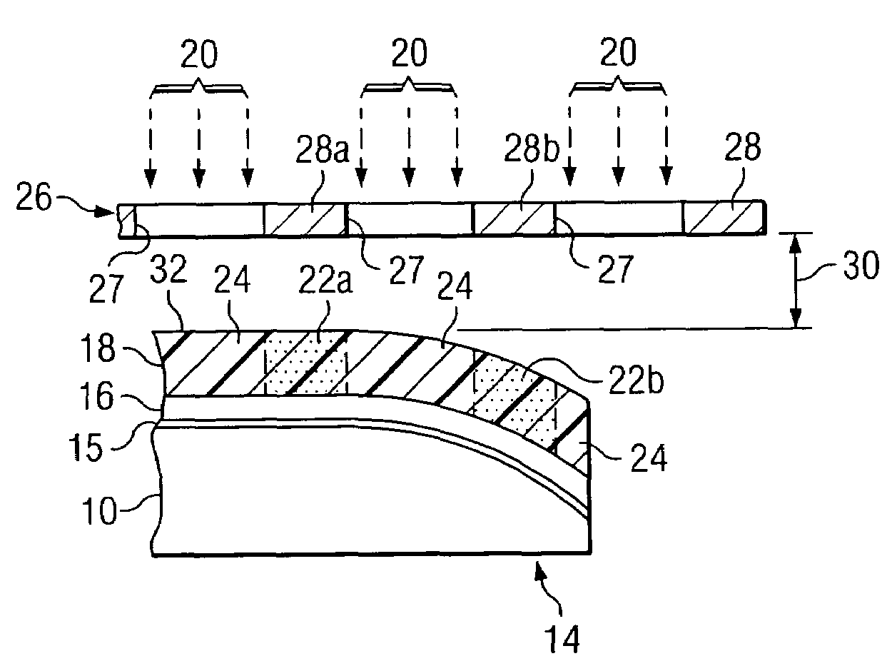
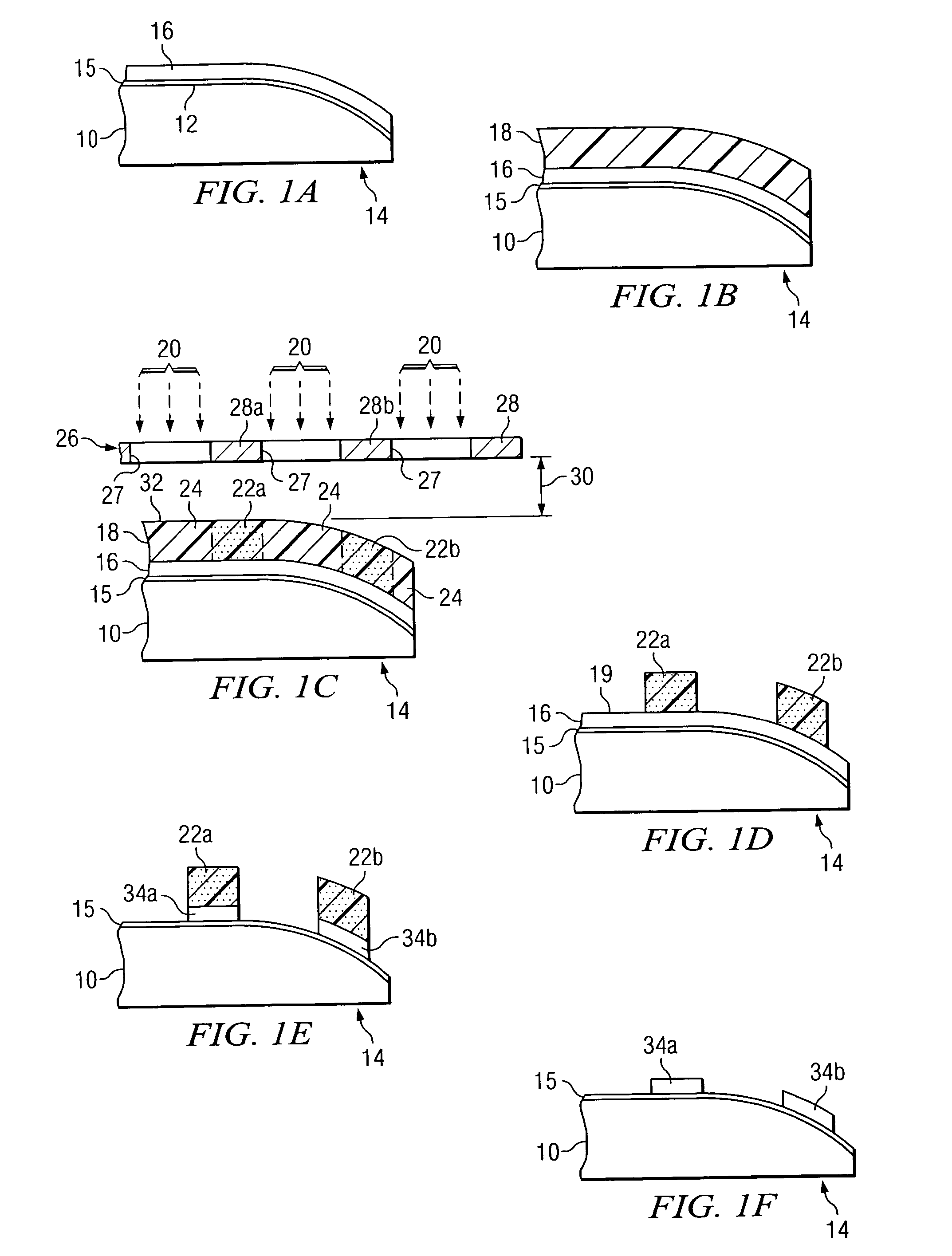
[0003]From the foregoing it may be appreciated by those skilled in the art that a need has arisen for a system and method for exposure of partial edge shot on a wafer. In accordance with the present invention, a system and method for forming semiconductor devices on the surface of the wafer is provided that substantially eliminates or greatly reduces disadvantages and problems associated with conventional semiconductor fabrication equipment.

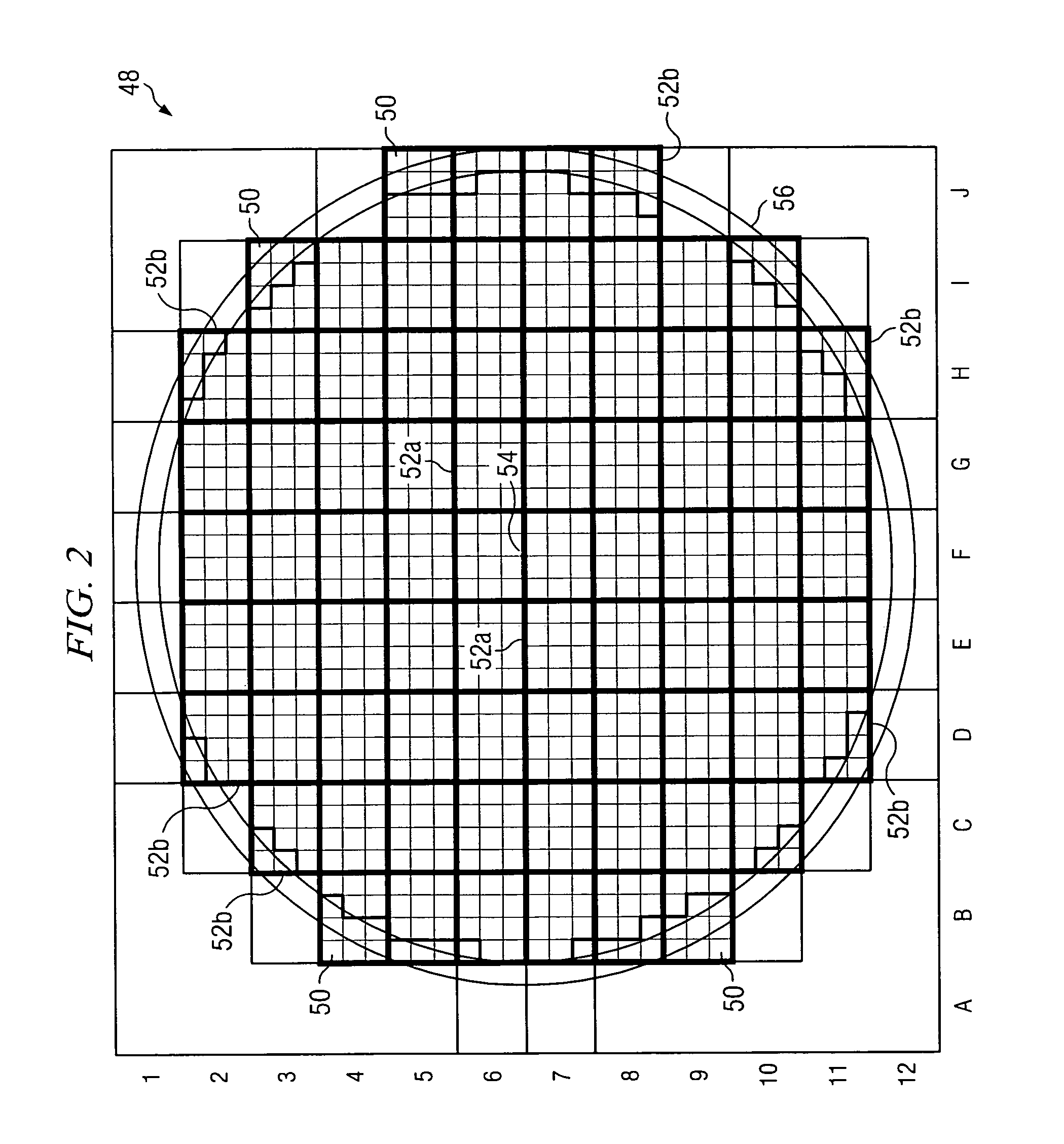
[0004]According to one embodiment of the present invention, a method of forming a semiconductor device includes forming a photoresist layer on the surface of a wafer. The wafer includes an array of die that includes a plurality of complete die and at least one partial edge die. The wafer has an edge that has a substantially rounded profile causing undersized patterns in semiconductor devices formed on partial edge die. A first exposure intensity is assigned to a first group of die on the surface of the wafer. The first group of die includes a gro...


PUM

PropertyMeasurementUnit
thicknessaaaaaaaaaa
diameteraaaaaaaaaa
widthaaaaaaaaaa

Abstract

According to one embodiment of the present invention, a method of forming a semiconductor device includes forming a photoresist layer on a surface of a wafer. The wafer includes an array of die that includes a plurality of complete die and at least one partial edge die. The wafer has an edge that has a substantially rounded profile causing undersized patterns in semiconductor devices formed on partial edge die. A first exposure intensity is assigned to a first group of die on the surface of the wafer. The first group of die includes a group of complete die, and the first exposure intensity is assigned based at least in part on the location of the first group of die on the surface of the wafer. A second exposure intensity is assigned to a second group of die on the surface of the wafer. The second group of die includes at least one partial edge die. The second exposure intensity less than the first exposure intensity to compensate for reduced line width due to the wafer edge topography. Energy is directed at the second group of die at the second exposure intensity to avoid over-exposure of the second group of die.

Description

TECHNICAL FIELD OF THE INVENTION[0001]This invention relates generally to the field of semiconductor devices and, more particularly, to a system and method for the exposure of partial edge die.BACKGROUND OF THE INVENTION[0002]A scanner or other light source may be used during conventional fabrication processes to form devices or features on the surface of a wafer. Specifically, a light source may be operated to generate a beam of energy which is directed at a portion of the wafer. The energy transmitted from the light source through a mask is typically directed onto the wafer surface to cover a spatial area called the “shot” area. The shot area generally covers a group of die on the wafer or a single die depending on the size of the die and the configuration of the mask. Although a wafer has a generally horizontal surface on which the features are formed, the edge of the wafer is typically rounded such that the wafer has a substantially rounded profile. Typically, the light source i...

Claims


Application Information

Patent Timeline
Patent Type & Authority Patents(United States)
IPC IPC(8): G03F7/00
CPCG03F7/70425G03F7/70558
Inventor ATKINSON, CHRIS D.GULDI, RICHARD L.DETWEILER, SHANGTING
Owner TEXAS INSTR INC
Learn More