
Medical procedure

a technology of cooling element and cooling chamber, which is applied in the field of medical procedures, can solve the problems of emboli release into the brachiocephalic, carotid or subclavian arteries with serious consequences, difficult surgery upon the heart, and significant complications, and achieve the effect of reducing the risk of ischemia, reducing the risk of cardiac arrythmia and myocardial ischemia

Inactive Publication Date: 2008-05-13
ZOLL CIRCULATION
View PDF466 Cites 28 Cited by
  • Summary
  • Abstract
  • Description
  • Claims
  • Application Information

AI Technical Summary

Benefits of technology

The present invention provides a method and system for conducting a coronary bypass procedure using a heat transfer element to cool the patient's body and support the circulation using an intracorporeal pump. The method involves positioning a heat transfer element in a blood vessel and cooling the body to a temperature of about 35°C. The heart is then arrested or nearly arrested during the cooling process. The invention allows for efficient heat transfer and easy insertion of the heat transfer element, as well as high surface area to increase heat transfer. The system includes an inflatable inlet and outlet lumen with a structure to induce turbulence in the working fluid. The invention provides a solution for changing the temperature of blood in a safe and effective manner during a coronary bypass procedure.

Problems solved by technology

The arrest or stoppage of the heart is generally carried out because the constant pumping motion of the beating heart makes surgery upon the heart difficult.
Unfortunately, significant complications may result from such procedures.
For example, application of an external cross-clamp to a calcified or atheromatous aorta may cause the release of emboli into the brachiocephalic, carotid or subclavian arteries with serious consequences such as strokes.
Nonetheless, distortion is not eliminated, and the risk of emboli release remains present.
Other complications can arise from the cardiopulmonary bypass system, which includes mechanical blood pumps, an oxygenator, a heat exchanger, blood reservoirs and filters, and several feet of tubing to transport the blood from the patient on the operating table to the heart-lung machine located nearby and back to the patient.
Such systems can cause complications due to the exposure of blood to foreign surfaces, which result in the activation of virtually all the humoral and cellular components of the inflammatory response, as well as some of the slower reacting specific immune responses.
This may, in turn, increase the risk of hemorrhage.
The additional blood, if from a source other than the patient, may expose the patient to blood-borne diseases.
The technique of operating on the beating heart, however, is difficult, due to the rapid movement of the heart, and can at present only be applied to single vessel bypassing procedures.
Unfortunately, it can be difficult to provide adequate circulation with a pump of this type, increasing the risk of ischemia.
Moreover, while many of the dangers associated with cardiopulmonary bypass systems are avoided, certain benefits of such a system are also lost.
Unfortunately, as in the above case wherein the Hemopump supports circulation, these techniques result in less than ideal circulation and do not provide a hypothermic effect, increasing the risk of ischemia.
However, in such patients, hypothermia activates the sympathetic nervous system, resulting in a significant norepinephrine response.
Norepinephrine, in turn, binds to beta-receptor sites, including those in the heart, causing the heart to beat harder and more rapidly, frequently resulting in cardiac arrythmia and increasing the risk of myocardial ischemia.
Norepinephrine also causes peripheral vasoconstriction, frustrating relief of patient discomfort, for example, by using heating blankets.

Method used


Image

  • Medical procedure
  • Medical procedure
  • Medical procedure

Examples


Embodiment Construction

[0062]The present invention now will be described more fully hereinafter. This invention may, however, be embodied in different forms and should not be construed as limited to the embodiments set forth herein.

[0063]According to one aspect of the present invention, a procedure is provided by which a surgeon is able to perform a coronary bypass procedure with hypothermic protection, while at the same time avoiding many of the disadvantages associated with the use of traditional external cardiopulmonary bypass systems and aortic clamping procedures.

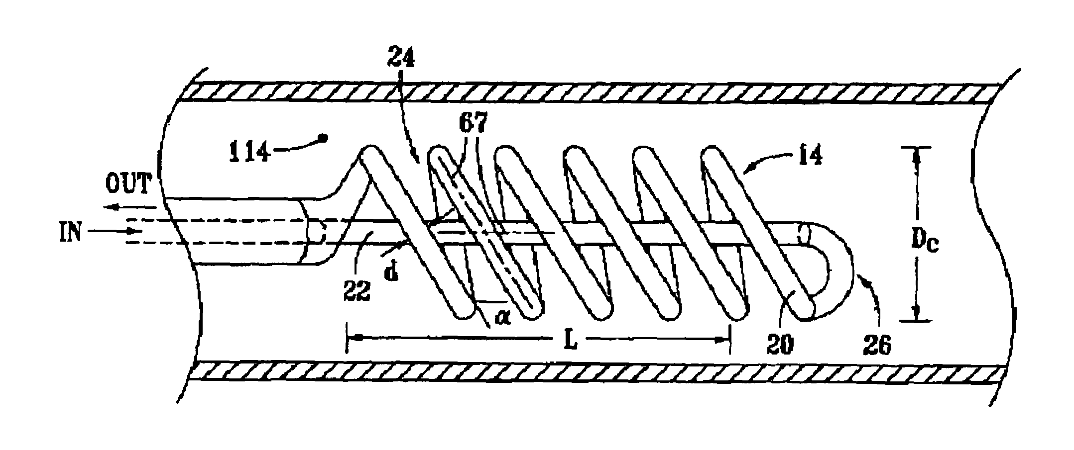
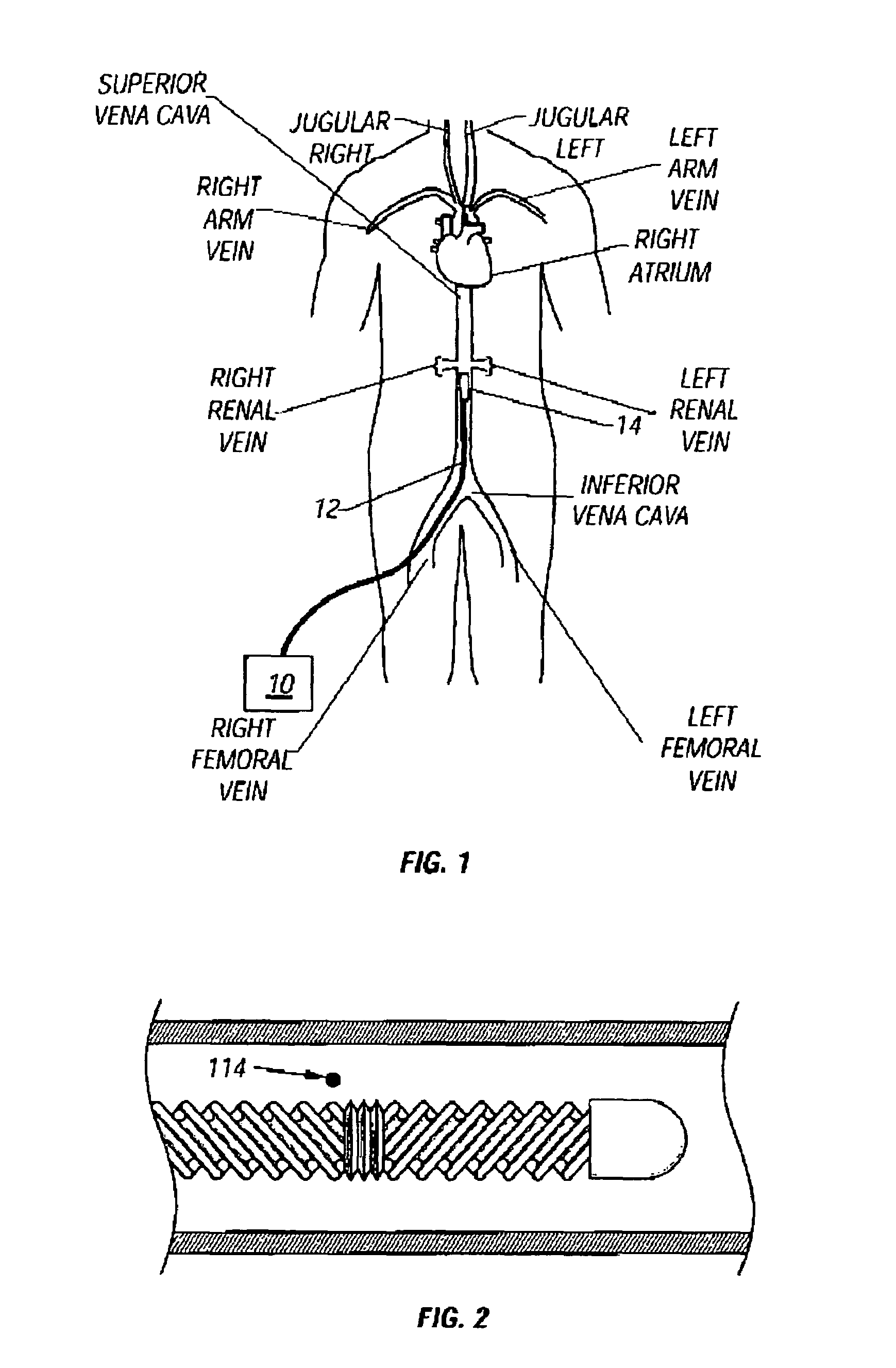
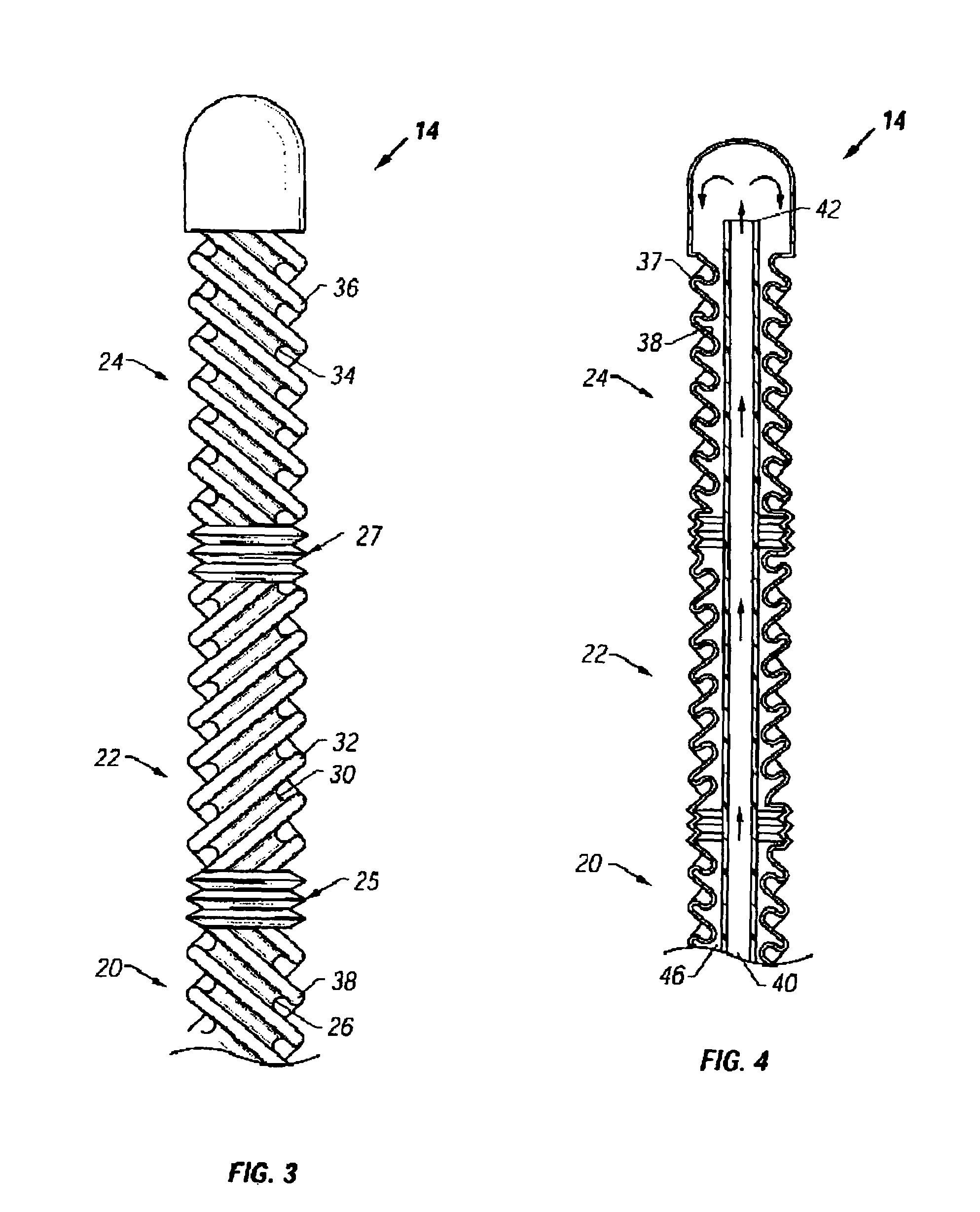
[0064]In one embodiment of the present invention, a heat transfer element is provided within a blood vessel of the body such that blood is cooled in vivo upon contact with the heat transfer element.

[0065]The heat transfer element can be provided in either arterial or venous blood vessels. One preferred location for the heat transfer element is the inferior vena cava, which typically ranges from 15 mm to 25 mm in diameter. A preferred method ...


PUM


Abstract

The use of an intravascular cooling element to induce hypothermia in connection with a medical procedure. According to a first aspect of the present, invention, a coronary bypass procedure is conducted in which a patient's blood is oxygenated with the patient's lungs and in which blood is circulated using the patient's heart or using an intracorporeal pump. The procedure preferably comprises: (a) positioning a heat transfer element in a blood vessel of a patient; (b) cooling the body of the patient to less than 35° C., more preferably 32±2° C., using the heat transfer element; and (c) forming a fluid communicating graft between an arterial blood supply and the coronary artery. The body of the patient is preferably heated to about 37° C. using the heat transfer element subsequent to the step of forming the fluid communicating graft. According to a further aspect of the invention, a hypothermic medical procedure is provided while a patient is in a conscious or semiconscious state, comprising (a) administering a beta-blocking drug to the patient; (b) delivering a heat transfer element to a blood vessel of the patient; and (c) cooling a region of the patient or the body of the patient to less than 35° C. using the heat transfer element.

Description

STATEMENT OF RELATED APPLICATIONS[0001]This application is a continuation-in-part of U.S. patent application Ser. No. 10 / 714,070, filed Nov. 14, 2003, which is a continuation of U.S. patent application Ser. No. 10 / 095,753, filed Mar. 11, 2002, now U.S. Pat. No. 6,695,873, which is a divisional of U.S. patent application Ser. No. 09 / 757,124, filed Jan. 8, 2001, now U.S. Pat. No. 6,540,771, which is a divisional of U.S. patent application Ser. No. 09 / 215,038, filed Dec. 16, 1998, now U.S. Pat. No. 6,261,312, which is a continuation-in-part of U.S. patent application Ser. No. 09 / 103,342, filed Jun. 23, 1998, now U.S. Pat. No. 6,096,068, which is a continuation-in-part of U.S. patent application Ser. No. 09 / 047,012, filed Mar. 24, 1998, now U.S. Pat. No. 5,957,963, which is a continuation-in-part of U.S. patent application Ser. No. 09 / 012,287, filed Jan. 23, 1998, now U.S. Pat. No. 6,051,019. Each of these disclosures is hereby incorporated by reference in its entirety.[0002]This applic...

Claims


Application Information

Patent Timeline
Patent Type & Authority Patents(United States)
IPC IPC(8): A61F7/00A61B17/00A61B18/02A61F7/02A61F7/12
CPCA61B18/02A61F7/12A61F7/123A61B2017/00292A61B2018/0022A61B2018/0212A61B2018/0262A61F2007/0056A61F2007/0288A61F2007/126
Inventor DOBAK, III, JOHN D.
Owner ZOLL CIRCULATION
Learn More