Eureka AIR delivers breakthrough ideas for toughest innovation challenges, trusted by R&D personnel around the world.

Arrangement and method for metering target material for the generation of short-wavelength electromagnetic radiation

a technology of electromagnetic radiation and target material, which is applied in the direction of x-ray tube electrodes, x-ray tubes with very high current, radiation therapy, etc., to achieve the effect of minimizing the gas burden in the interaction chamber and generating debris

Inactive Publication Date: 2008-05-06
XTREME TECH
View PDF17 Cites 10 Cited by
  • Summary
  • Abstract
  • Description
  • Claims
  • Application Information

AI Technical Summary

Benefits of technology

[0017]It is the object of the invention to find a novel possibility for metering target material for the generation of short-wavelength electromagnetic radiation, in particular X radiation and EUV radiation, from an energy beam induced plasma which makes it possible to provide reproducibly supplied mass-limited targets in such a way that only the amount of target material for plasma generation that can be effectively converted to radiating plasma in the desired wavelength region arrives in the interaction chamber and, therefore, debris generation and the gas burden in the interaction chamber are minimized.
[0018]In an arrangement for metering target material for the generation of short-wavelength electromagnetic radiation, in particular EUV radiation, in which a target generator is arranged for providing target material along a given target path and an energy beam for generating a radiation emitting plasma is directed to the target path, the above-stated object is met, according to the invention, in that the target generator has an injection device which contains a nozzle chamber with nozzle and which is connected with a reservoir, wherein means are provided at the nozzle chamber for a defined, temporary pressure increase in order to introduce an individual target into the interaction chamber at the interaction point exclusively when required for the generation of plasma, and in that means are arranged for adjusting an equilibrium pressure in the nozzle in order to compensate for a pressure drop at the nozzle of the injection device resulting from the pressure difference between the vacuum pressure in the interaction chamber and the pressure exerted on the target material in the reservoir, wherein the adjusted equilibrium pressure prevents the escape of target material as long as there is no temporary pressure increase in the nozzle chamber.
[0019]A piezo element is advantageously provided as means for the pressure increase in the nozzle chamber. The piezo element causes a reduction in the volume of the nozzle chamber by means of inward displacement of a wall of the nozzle chamber. For this purpose, the nozzle chamber preferably has a membrane wall which is pressed into the interior of the nozzle chamber when voltage is applied to the piezo element. However, a piezo stack can also advisably be arranged inside the nozzle chamber for reducing the volume of the chamber.

Problems solved by technology

Excess target material that is vaporized or sublimated or which, although ionized, is not excited by the energy beam to a sufficient degree for the desired radiation emission (marginal area or immediate surroundings of the interaction point) causes not only increased emission of debris but also an unwanted gas atmosphere in the interaction chamber which in turn contributes considerably to an absorption of the short-wavelength EUV radiation generated from the plasma.
These are listed in the following along with their characteristic disadvantages:Continuous liquid jet, possibly also frozen (solid consistency) (EP 0 895 706 B1)Mass limiting can be realized only to a limited extent because of the large size of the target in one linear dimension, resulting in increased debris and an unwanted gas burden in the vacuum chamber.The shock wave proceeding from the plasma expansion (with slight damping) in the target jet in the direction of the target nozzle leads to a certain destruction of the target flow and, therefore, to a limiting of the pulse repetition rate of the laser excitation.Clusters (U.S. Pat. No. 5,577,092), gas puffs (Fiedorowicz et al., SPIE Proceedings, Vol. 4688, 619) and aerosols (WO 01 / 30122 A1; U.S. Pat. No. 6,324,256 B1)lead to severe nozzle erosion with short distances between the interaction point and the target nozzle and, at large distances from the nozzle (due to dramatically decreasing average density of the target), to a low efficiency of the radiation emission of the plasma.Continuous flow of individual droplets (EP 0 186 491 B1)requires precise synchronization with the excitation laser,cold target material in the vicinity of the plasma (less than with the target jet, but still present) is vaporized and leads to absorbent gas atmosphere and increased debris.
Apart from increased generation of debris, this leads to excess target material in the interaction chamber which causes an increased gas burden (particularly when xenon is used as target) and, therefore, an increased pressure in the interaction chamber.
The increased gas burden leads in turn to an unwanted increase in the absorption of radiation emitted by the plasma.
Further, the unused target material leads to increased material consumption and accordingly raises costs unnecessarily.

Method used


Image

  • Arrangement and method for metering target material for the generation of short-wavelength electromagnetic radiation
  • Arrangement and method for metering target material for the generation of short-wavelength electromagnetic radiation
  • Arrangement and method for metering target material for the generation of short-wavelength electromagnetic radiation

Examples


Embodiment Construction

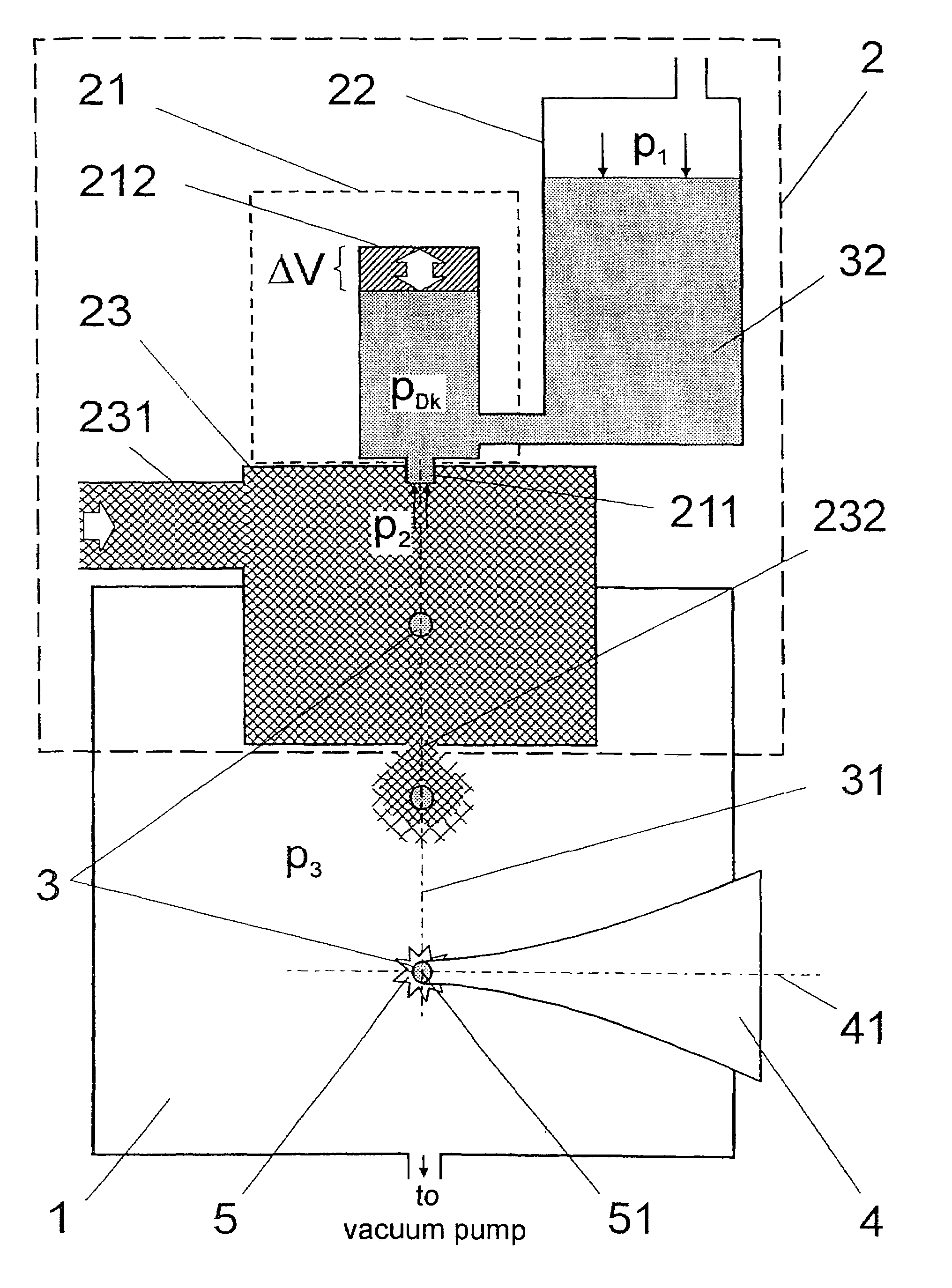
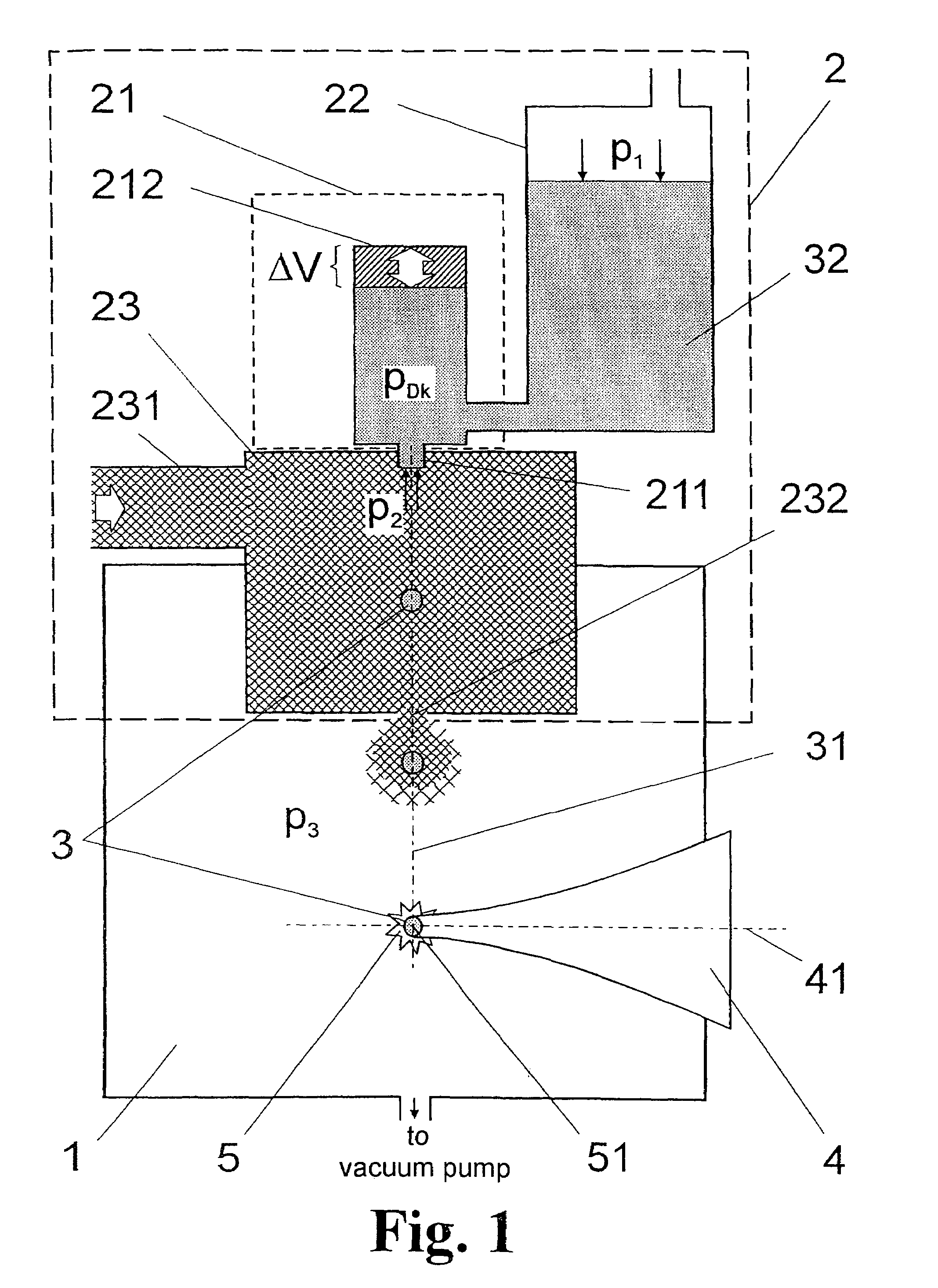
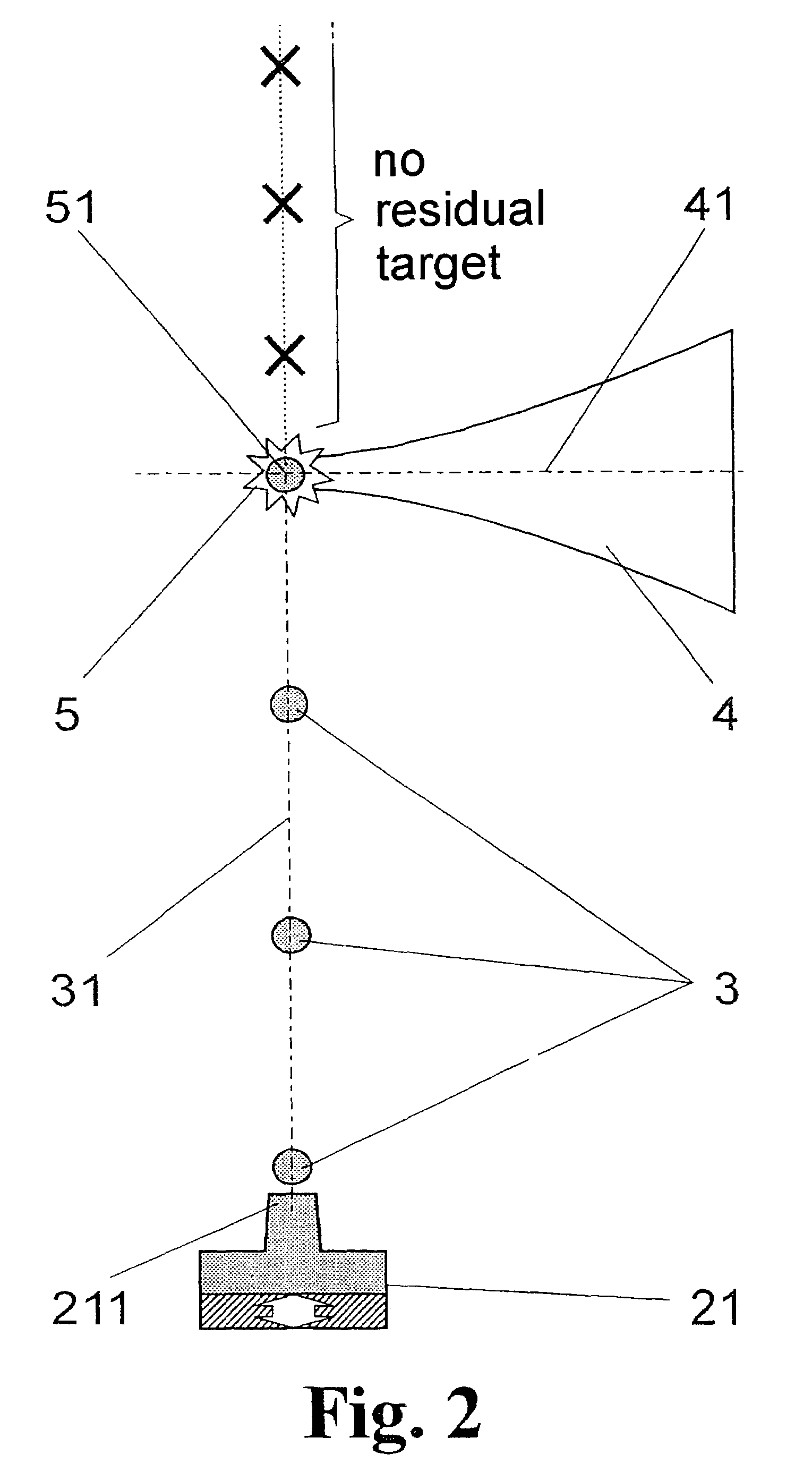
[0049]FIG. 1 is a schematic view showing a portion of a radiation source for generating short-wavelength electromagnetic radiation based on a plasma induced by the input of energy. The drawing shows an interaction chamber 1 in which individual targets 3 are prepared along a target path 31 by a target generator 2. The target path 31 is intersected by the axis 41 of an energy beam 4 at an interaction point 51, wherein a plasma 5 emitting the desired radiation is generated by the energy beam 4 impinging on a respective individual target 3.

[0050]The target generator 2 comprises an injection device 21 with a nozzle 211 and a nozzle chamber 212 which is able to cause a temporary change in volume ΔV and, therefore, a change in pressure of the nozzle chamber pressure PDk. The principle is similar to that of conventional inkjet nozzles and will be described in more detail (FIG. 3 and FIG. 4) in the following. Further, the injection device 21 of the nozzle chamber 212 is connected to a reserv...


PUM


Abstract

The invention is directed to an arrangement for metering target material for the generation of short-wavelength electromagnetic radiation from an energy beam induced plasma, in particular X radiation and EUV radiation. The object of the invention is to find a novel possibility for metering target material for the generation of short-wavelength electromagnetic radiation from an energy beam induced plasma which makes it possible to provide reproducibly supplied mass-limited targets in such a way that only the amount of target material for plasma generation that can be effectively converted to radiating plasma in the desired wavelength region arrives in the interaction chamber and, therefore, debris generation and the gas burden in the interaction chamber are minimized. This object is met, according to the invention, in that an injection device is provided for target generation, wherein means are arranged upstream of the nozzle in a nozzle chamber for a defined, temporary pressure increase in order to introduce an individual target into the interaction chamber exclusively when required, and an antechamber is arranged around the nozzle for generating a quasistatic pressure upstream of the interaction chamber, wherein an equilibrium pressure in the antechamber prevents the escape of target material as long as there is no pressure increase in the nozzle chamber.

Description

CROSS-REFERENCE TO RELATED APPLICATIONS[0001]This application claims priority of German Application No. 10 2004 036 441.9, filed Jul. 23, 2004, the complete disclosure of which is hereby incorporated by reference.BACKGROUND OF THE INVENTION[0002]a) Field of the Invention[0003]The invention is directed to an arrangement and a method for metering target material for the generation of short-wavelength electromagnetic radiation from an energy beam induced plasma. It is applied in particular in EUV radiation sources for projection lithography in semiconductor chip fabrication.[0004]b) Description to the Related Art[0005]Reproducible mass-limited targets for pulsed energy input for plasma generation have gained acceptance, above all in radiation sources for projection lithography, because they minimize unwanted particle emission (debris) compared to other types of targets. An ideal mass-limited target is characterized in that the particle number in the focus of the energy beam is limited ...

Claims


Application Information

Patent Timeline
Patent Type & Authority Patents(United States)
IPC IPC(8): H05G2/00
CPCH05G2/003H05G2/006H05G2/005
Inventor HERGENHAN, GUIDOKLOEPFEL, DIETHARD
Owner XTREME TECH
Why Eureka
Eureka Blog
Learn More