
Method for efficiently determining a DNA strand break

a dna strand and efficient technology, applied in the field of dna strand break efficiently determination, can solve the problems of aging, cell death, tumorigenesis or carcinogenesis, dna strand break is a particularly serious form of dna damage, and has a particularly deleterious effect on cells, so as to achieve specific binding activity, specifically and sensitively detect dna strand break(s)

Inactive Publication Date: 2008-04-22
JAPAN ATOMIC ENERGY AGENCY INDEPENDANT ADMINISTRATIVE CORP
View PDF3 Cites 5 Cited by
  • Summary
  • Abstract
  • Description
  • Claims
  • Application Information

AI Technical Summary

Benefits of technology

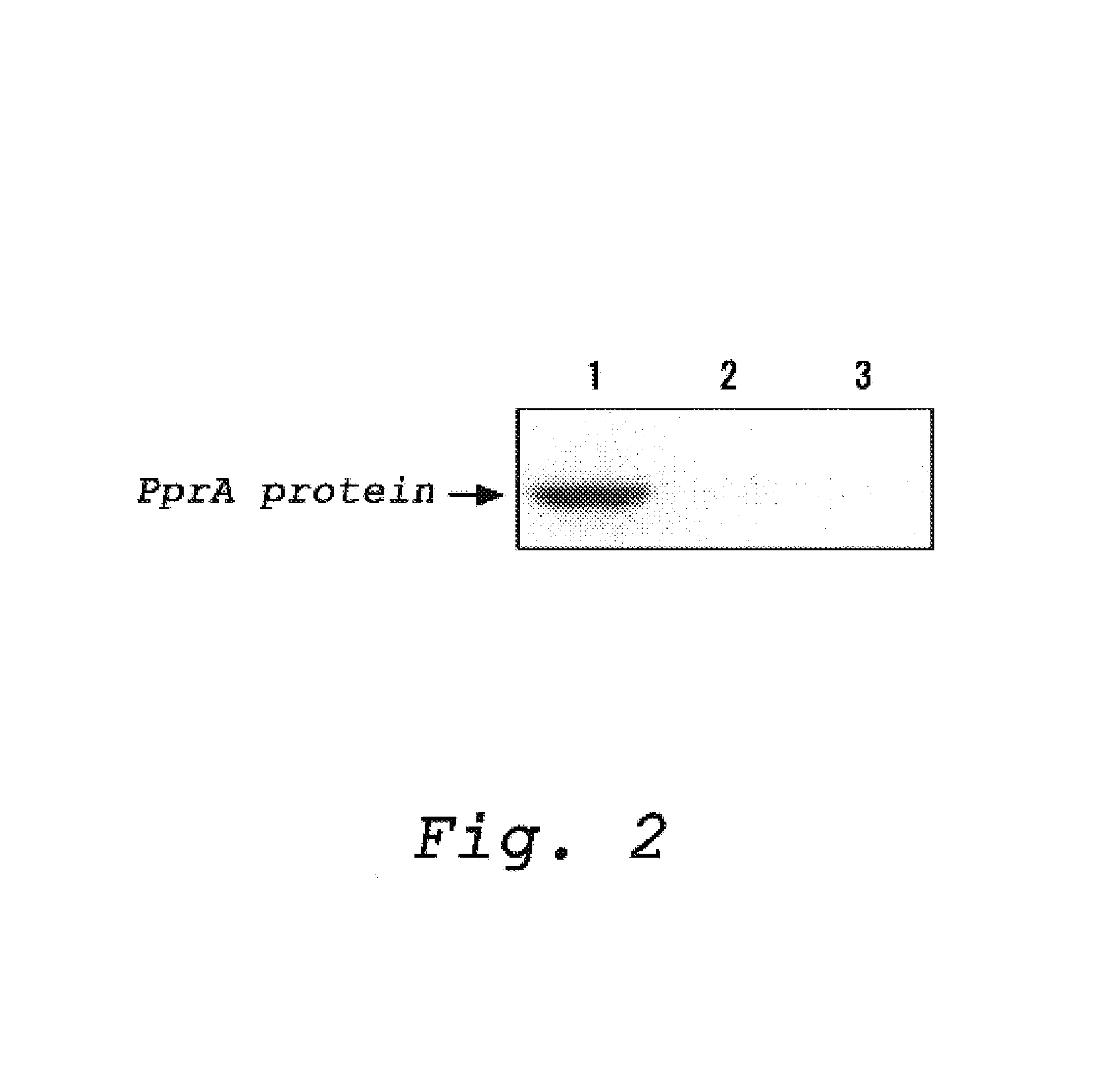
[0008]In view of the problems existing in the prior art, the present inventors conducted extensive studies with the aim of developing a method for detecting a DNA strand break using a protein which has a potent and specific binding activity to the DNA strand break. As a result, the present inventors determined that it is possible to specifically and sensitively detect DNA strand break(s) in a sample by binding a Ppra protein derived from Deinococcus radiodurans to a DNA strand break and by detecting the Ppra protein bound to the DNA strand break and, as a result, completed the present invention.

Problems solved by technology

However, living organisms are continually exposed to environmental factors which trigger damage to DNA.
Such DNA damage inhibits the replication or transcription of DNA, resulting in mutation which may cause cell death, aging, tumorigenesis or carcinogenesis.
A DNA strand break is a particularly serious form of DNA damage and has an especially deleterious effect on cells.
However, to date there has existed no known sufficiently sensitive method for directly detecting a life-threatening DNA strand break.
This was resulted in a delay in technical progress in the art.
However, since endogenous DNA binding proteins are used in these methods for detecting DNA strand break(s), these methods have disadvantages that DNA strand break(s) cannot be detected in a sample which is prepared from an organism not having such DNA binding proteins, and that it is difficult to detect initial damage of DNA because it takes a certain period to bind DNA binding protein to DNA strand break(s).

Method used


Image

  • Method for efficiently determining a DNA strand break
  • Method for efficiently determining a DNA strand break
  • Method for efficiently determining a DNA strand break

Examples


example 1

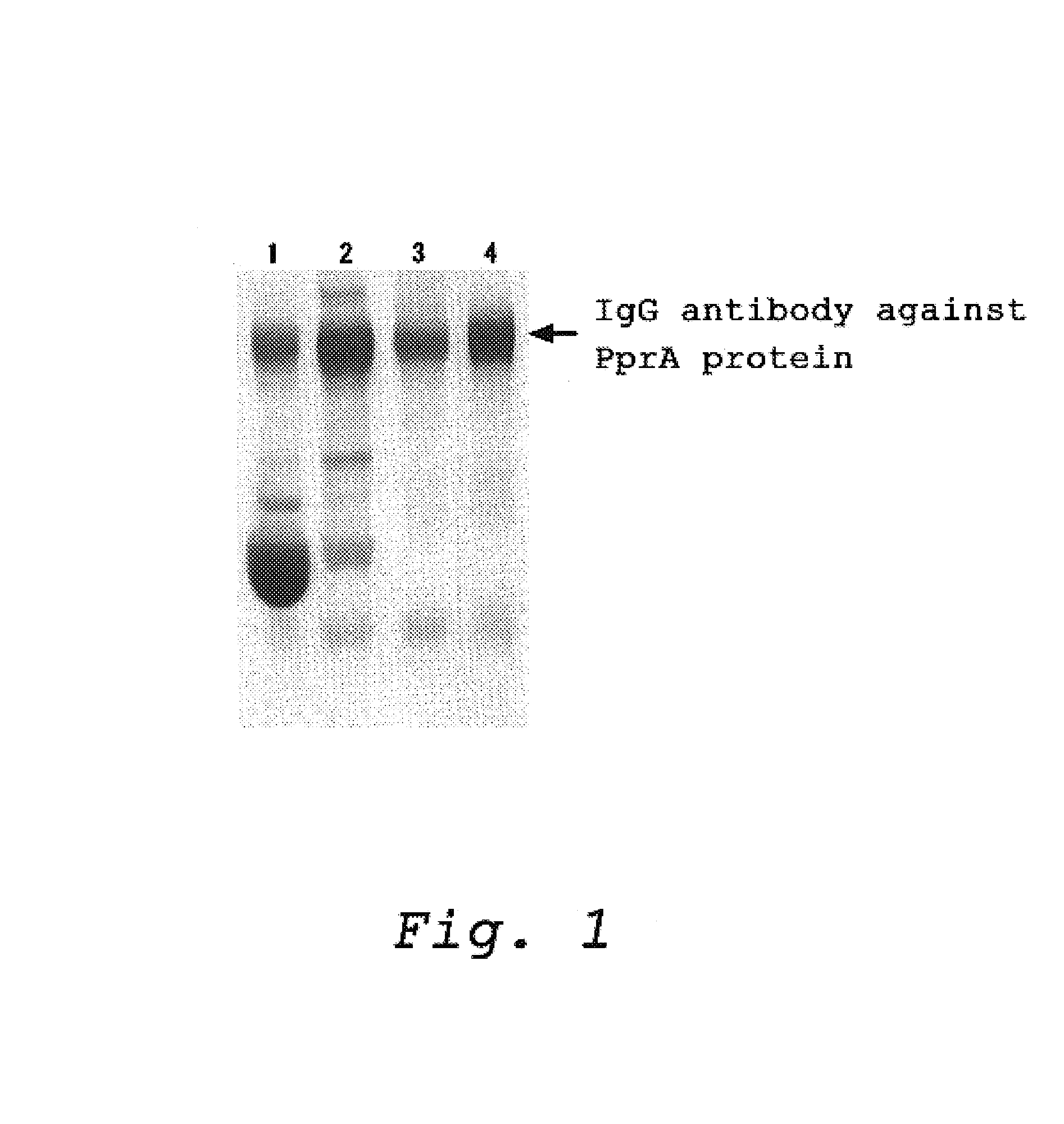
Production of a Polyclonal Antibody which Recognize a Protein Having an Ability to Recognize and Bind to DNA Strand Break (PprA)

[0034](1) Preparation of the PprA Protein

[0035]The protein, PprA, was prepared according to the method described in Japanese Patent Public Diclosure No. 2003-052376 (JP-A-052376 / 2003, corresponding to Japanese patent application No. 246260 / 2001). More specifically, the protein, PprA, was prepared by the method below:

[0036]PCR was carried out using a full-length pprA gene encoding the PprA protein which was contained in a plasmid as a template and primers (primer 1: 5′-gggcataata aaggccatat ggcaagggct aaagc-3′ (SEQ ID NO: 3) and primer 2: 5′-ttttggatcc tcagctctcg cgcaggccgt gc-3′ (SEQ ID NO: 4)) to amplify the gene pprA having 855 bp of an open reading frame (SEQ ID NO: 2). The pprA gene was integrated into E. coli expression vector pET3a (Novagen) to prepare an expression vector called pET3pprAwt.

[0037]Then, the pET3pprAwt plasmid as prepared above was used...

example 2

A Method for Detecting a DNA Strand Break In a Mammalian Cell Nucleus Using a Protein Having an Activity to Recognize and Bind to a DNA Strand Break and an Antibody which Specifically Binds Thereto

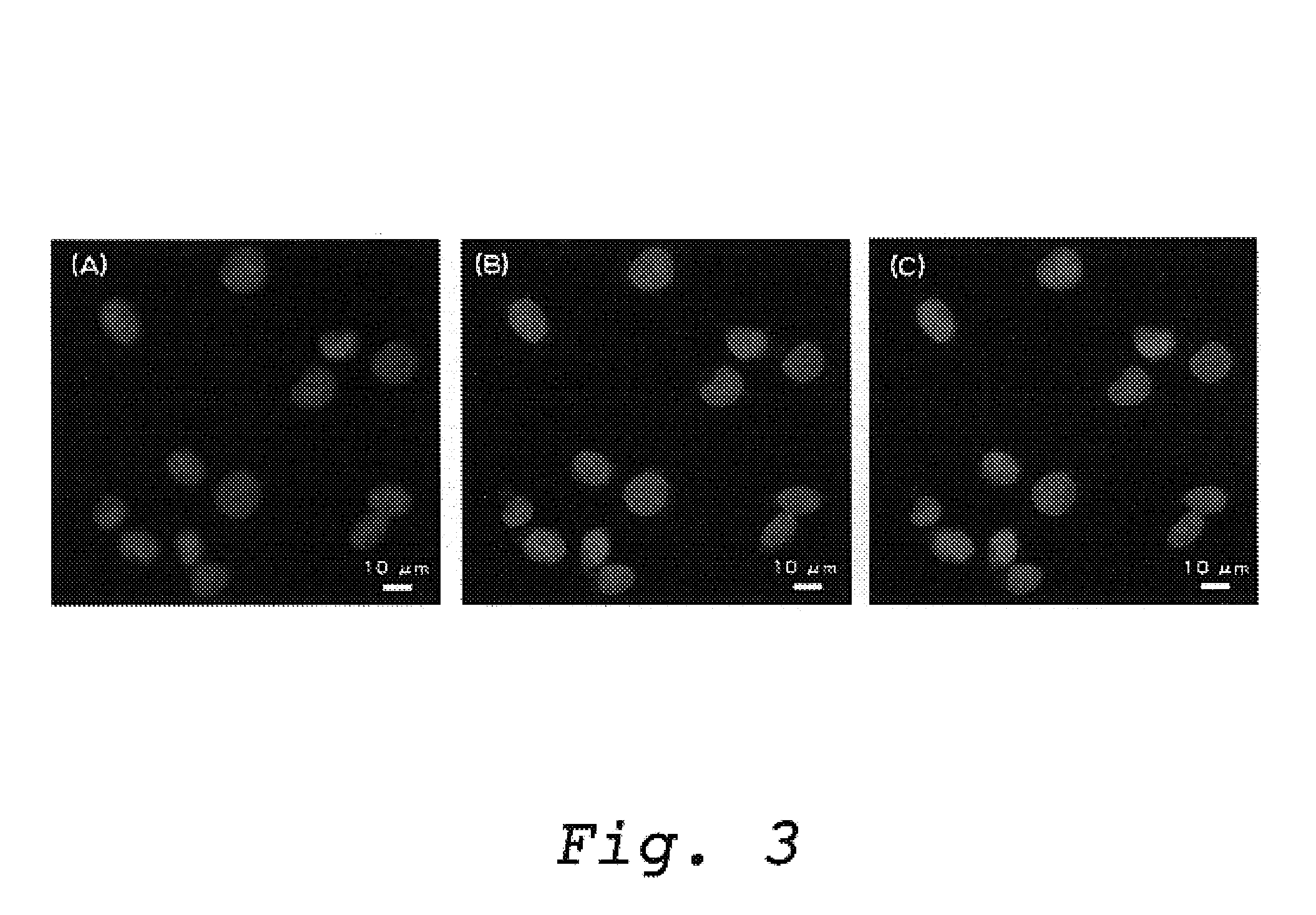
[0045]An example is shown here in which a DNA strand break induced by gamma ray irradiation within a nucleus of a fibroblast cell derived from Chinese hamster ovary (CHO-K1) could be detected using a protein having a DNA binding activity which was prepared in Example 1 and a fluorescent labeled polyclonal anti-PprA IgG antibody.

[0046](1) Preparation of Cells

[0047]CHO-K1 cells are cultured using Ham's F12 culture medium supplemented with 10% FCS in CO2 incubator (5% CO2) at 37° C. After removing the culture medium from a culture dish using an aspirator, the cells which were attached to the culture dish were washed twice using the bivalent ions free-phosphate buffered saline (PBS (−)). After washing, by adding PBS (−) containing 0.05% trypsin and 0.02% EDTA to the cells, and by stirring the ...

example 3

A Method for Detecting a DNA Strand Break in Mitochondria of Mammalian Cells Using a Protein Having an Ability to Recognize and Bind to a DNA Strand Break and an Antibody which Specifically Bind to the Protein

[0062]This example shows that a protein having an ability to recognize and bind to a DNA strand break as prepared in Example 1 and a fluorescence labeled IgG antibody are used to detect a DNA strand break generated by gamma ray irradiation in mitochondria DNA of CHO-K1 cells.

[0063]CHO-K1 cells which were adhered on a cover glass were prepared by the same method as Example 2-(1). MitoRed (excitation wavelength at 560 nm; Dojin kagaku), which can specifically stain mitochondria, was applied to the cells at a final concentration of 100 nM, which were incubated in CO2 incubator (5% CO2) for 60 minutes at 37° C. After incubation, the cells were irradiated with 0, 5, 10, and 20 Gy of gamma ray which were generated from 60Co as a radiation source using a similar method to that of Exam...


PUM

PropertyMeasurementUnit
Frequencyaaaaaaaaaa

Abstract

The present invention is directed to directly measure distribution in vivo and the frequency of generation in vivo of DNA strand breaks which induce cell death and mutations. The present inventors accomplished the present invention by providing a method for detecting a DNA strand break in a sample, which comprises a step of binding a PprA protein derived from Deinococcus radiodurans to a DNA strand break and a step of detecting the PprA protein which is bound to the DNA strand break; as well as by providing a kit for detecting a DNA strand break in a sample which comprises PprA proteins derived from Deinococcus radiodurans and a means for detecting a PprA protein which is bound to a DNA strand break.

Description

BACKGROUND OF THE INVENTION[0001]This application is based upon and claims the benefit of priority from Japanese Patent Application No. 2003-26303, filed on Feb. 3, 2003; the entire contents of this application are incorporated herein by reference.[0002]The present invention is directed to a method for detecting a DNA strand break using a PprA protein derived from Deinococcus radiodurans which recognizes and binds to a DNA strand break. The present invention is also directed to a kit for detecting one or more DNA strand break which comprises an amount of PprA protein derived from Deinococcus radiodurans which recognize and bind to one or more DNA strand break.[0003]It is essential for continued existence of species that DNA, a carrier of genetic information, be stably maintained, and transferred to progeny. However, living organisms are continually exposed to environmental factors which trigger damage to DNA. Such factors consist of extrinsic such as radiation, ultraviolet rays, age...

Claims


Application Information

Patent Timeline
IPC IPC(8): C12Q1/68G01N33/573G01N33/53C07K14/195C12N15/09G01N33/577
CPCC12Q1/68C12Q2522/101C12Q2521/514G01N2474/20Y10S435/81Y10S435/975
Inventor SATOH, KATSUYAWADA, SEIICHINARUMI, ISSAYKIKUCHI, MASAHIROFUNAYAMA, TOMOOKOBAYASHI, YASUHIKO
Owner JAPAN ATOMIC ENERGY AGENCY INDEPENDANT ADMINISTRATIVE CORP
Learn More