
Apparatus and process for preparing sorbents for mercury control at the point of use

Active Publication Date: 2008-04-22
ADA ES
View PDF117 Cites 81 Cited by
  • Summary
  • Abstract
  • Description
  • Claims
  • Application Information

AI Technical Summary

Benefits of technology

[0013]While not wishing to be bound by any theory, it is believed that the sometimes low contaminant removal rates of sorbents in commercial applications are due in large part to the agglomeration of particles during transportation from the manufacturer to the end user and during on-site storage before use. Agglomeration can dramatically change the effective particle size distribution. In other words, agglomeration can cause a larger mean and median sorbent particle size. When the sorbent is introduced into the gas stream, the larger particle size distribution provides, per unit of sorbent, fewer particles in the gas stream for contaminant sorbtion and removal. This can cause a substantially reduced sorbent removal efficiency. To attempt to overcome this problem, end users can introduce more sorbent per unit volume of gas stream, thereby resulting in much higher operating costs.
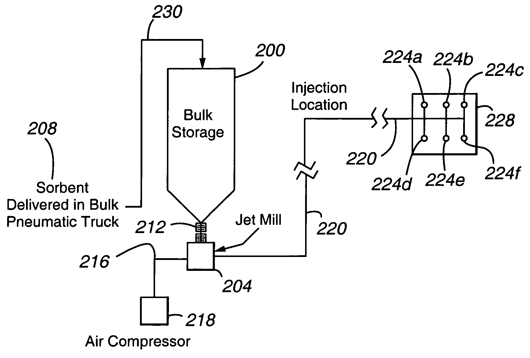
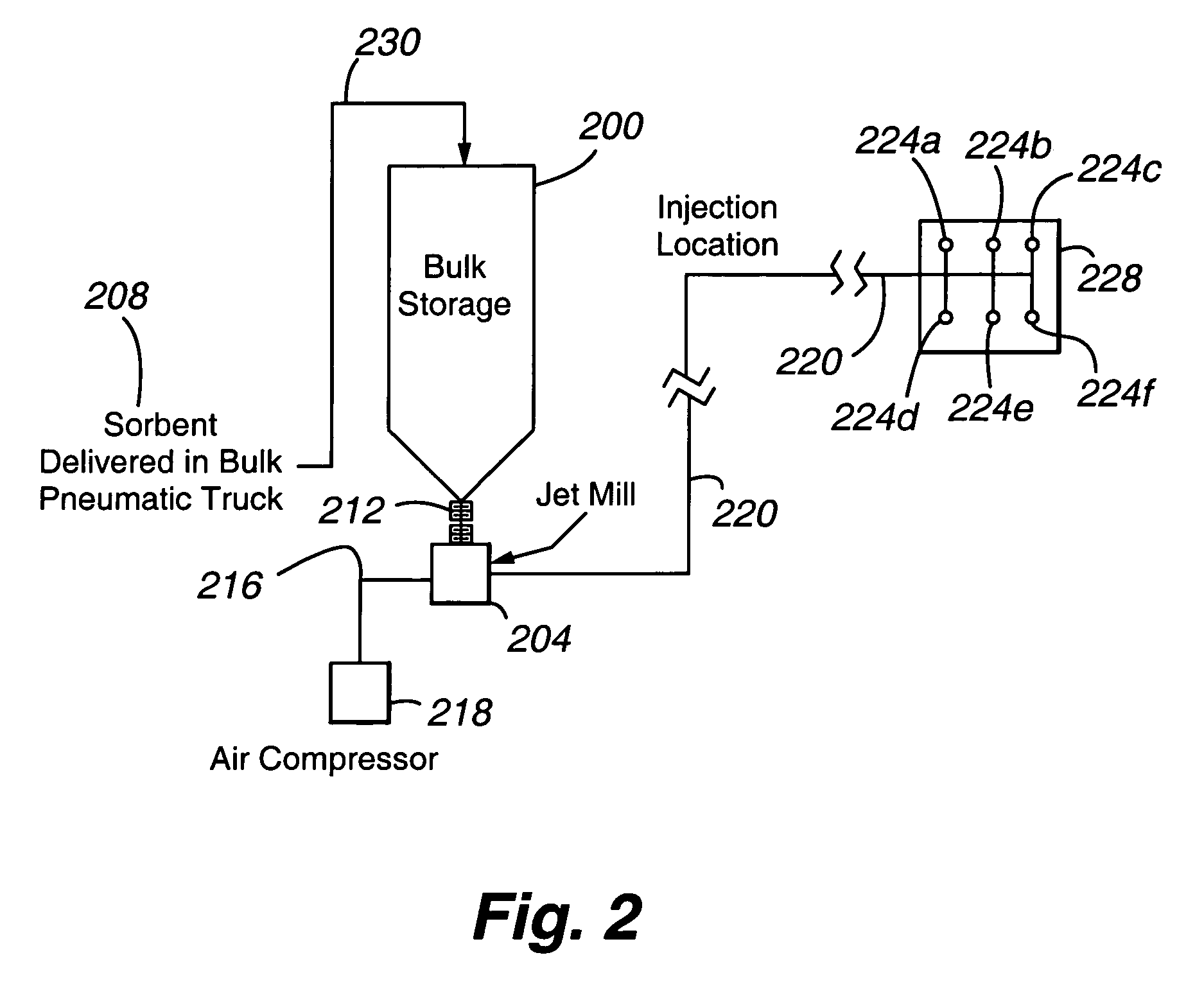
[0014]The method can have a number of benefits compared to existing processes. First, on-site milling can provide a sorbent particle size distribution that is relatively small and highly effective in removing contaminants. As will be appreciated, a finer particle size provides a greater number of particles in the gas stream for a given amount of sorbent, a high mass transfer rate to the gas stream, and a smaller interparticle distance in the gas stream. These factors can provide a higher rate of contaminant removal. On-site milling can also expose fresh, unreacted (more active) surfaces for contaminant capture. As will be appreciated, certain sorbents can react with the surrounding atmosphere when exposed to the atmosphere for prolonged periods, such as during shipping, thereby reducing the air toxic capacity of the sorbent. Second, the use of on-site milling permits the sorbent to be shipped as larger particles, thereby providing higher packing densities during shipment, greater ease of material handling, less product loss during transportation and handling, and lower transportation and operating costs. For example, raw (unmilled) activated carbon can be produced at centralized facilities, shipped to the end user site, and there processed (milled) to produce a desired particle size. As will be appreciated, the bulk density of the finished (milled) activated product is much less than the bulk density of raw activated carbon. Third, the sorbent processed on site can meet tighter specifications, particularly size distribution specifications. The on-site processed sorbent particles can, for example, have a narrower and smaller size distribution than milled sorbent particles shipped long distances. Fourth, on-site processing permits additional ingredients (such as other sorbents) to be introduced into the mill along with the sorbent to produce an enhanced sorbent material. The sorbent material, for instance, can be a customized blend having desired properties that is uniquely suited for the specific application.

Problems solved by technology

Vapor phase air toxics are commonly present in flue gas in trace concentrations of parts per million or less and therefore can be difficult to remove to comply with pertinent regulations.
While in flight, the carbon reacts with the entrained air toxics and binds the air toxics to the surfaces of the carbon.

Method used


Image

  • Apparatus and process for preparing sorbents for mercury control at the point of use
  • Apparatus and process for preparing sorbents for mercury control at the point of use
  • Apparatus and process for preparing sorbents for mercury control at the point of use

Examples


example 1

[0043]The following Example describes improved mercury control in flue gas achieved with finely ground sorbent particles.

[0044]This Example was carried out on the flue gas from an operating coal-fired power plant. A number of carbon sorbents, including DARCO FGD manufactured by Norit Americas (Marshall, Tex.) with a mass mean particle diameter of approximately 18 micrometers, was compared to DARCO INSUL, also manufactured by Norit Americas, with a mass mean particle diameter of approximately 6 micrometers, was injected into the flue gas, downstream of (i.e., after) an electrostatic precipitator (ESP), and upstream of a baghouse (fabric filter.) Flue gas temperature was approximately 300 degrees F. Mercury concentration was measured by a Semi-Continuous Emissions Monitor (S-CEM), in the following locations: upstream of the ESP and downstream of both the sorbent injection site and the baghouse.

[0045]FIG. 4 shows the results. The X-axis depicts the amount of carbon injected into the fl...


PUM

PropertyMeasurementUnit
Timeaaaaaaaaaa
Size distributionaaaaaaaaaa
Sizeaaaaaaaaaa

Abstract

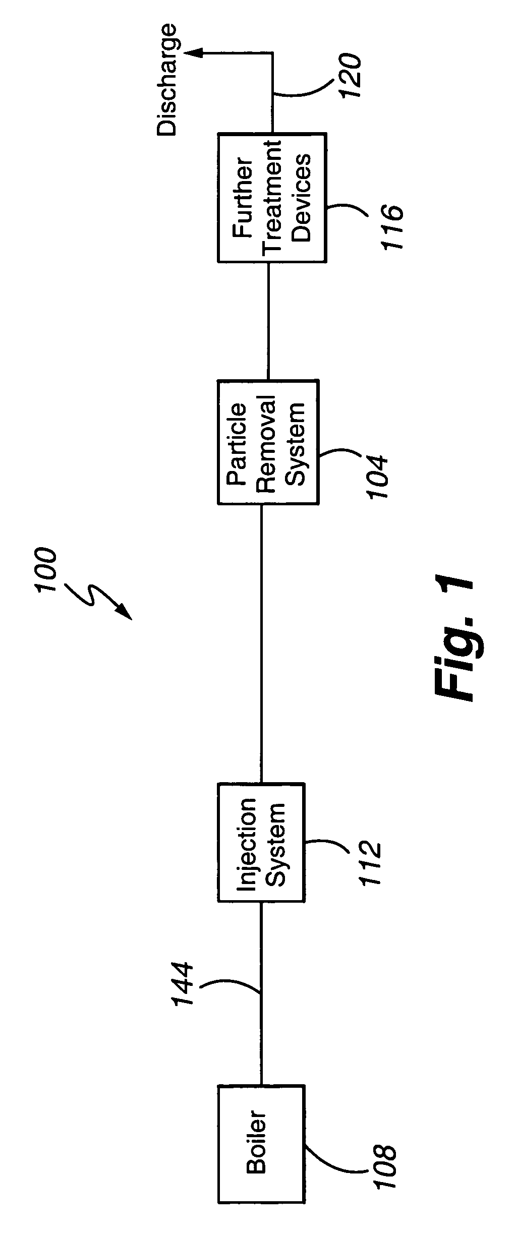
A system for treating a contaminated gas stream is provided that includes a comminution device 204 operable to effect size reduction of a plurality of sorbent particles and form a plurality of comminuted particles, a plurality of nozzles 224 distributed through the gas stream and operable to introduce the plurality of comminuted particles into the gas stream, and a particle removal device 104 operable to remove at least most of the introduced comminuted particles and form a treated gas stream. The comminution device is in direct fluid communication with the nozzles.

Description

CROSS REFERENCE TO RELATED APPLICATIONS[0001]The present application claims the benefit of U.S. Provisional Patent Application No. 60 / 460,478, filed Apr. 3, 2003, the entire disclosure of which is hereby incorporated herein by reference.FIELD OF THE INVENTION[0002]The present invention is directed generally to treatment of gases to remove controlled materials and specifically to the treatment of flue gases to remove mercury and other contaminants.BACKGROUND OF THE INVENTION[0003]Each year, the emission of air toxics from combustion sources is being subjected to increasingly strict regulations. These regulations include not only existing regulations, such as the U.S. Clean Air Act as amended in 1970, 1977, and 1990, the National Energy Act, and the National Primary and Secondary Ambient Air Quality Standards, but also pending regulations that will require the removal of certain air toxics from utility plant flue gas. Title III of the Amendments governs air toxics. As used herein, an ...

Claims


Application Information

Patent Timeline
IPC IPC(8): B01D53/64
CPCB01D53/10B01D2253/102B01D2253/304B01D2257/20B01D2257/602
Inventor DURHAM, MICHAEL D.MARTIN, CAMERON E.
Owner ADA ES
Learn More