
Multi-access system and method using multi-sectored antenna

a multi-sectored, multi-access technology, applied in diversity/multi-antenna systems, electromagnetic wave modulation, modulation, etc., can solve the problems of overburdening the wireless connection by exceeding its throughput capability, affecting communication, and data communication at the lower data rate may not be satisfactory for the intended application, so as to facilitate communication and improve gain, the effect of avoiding cost or complexity

Inactive Publication Date: 2008-04-15
MICROSOFT TECH LICENSING LLC
View PDF23 Cites 19 Cited by
  • Summary
  • Abstract
  • Description
  • Claims
  • Application Information

AI Technical Summary

Benefits of technology

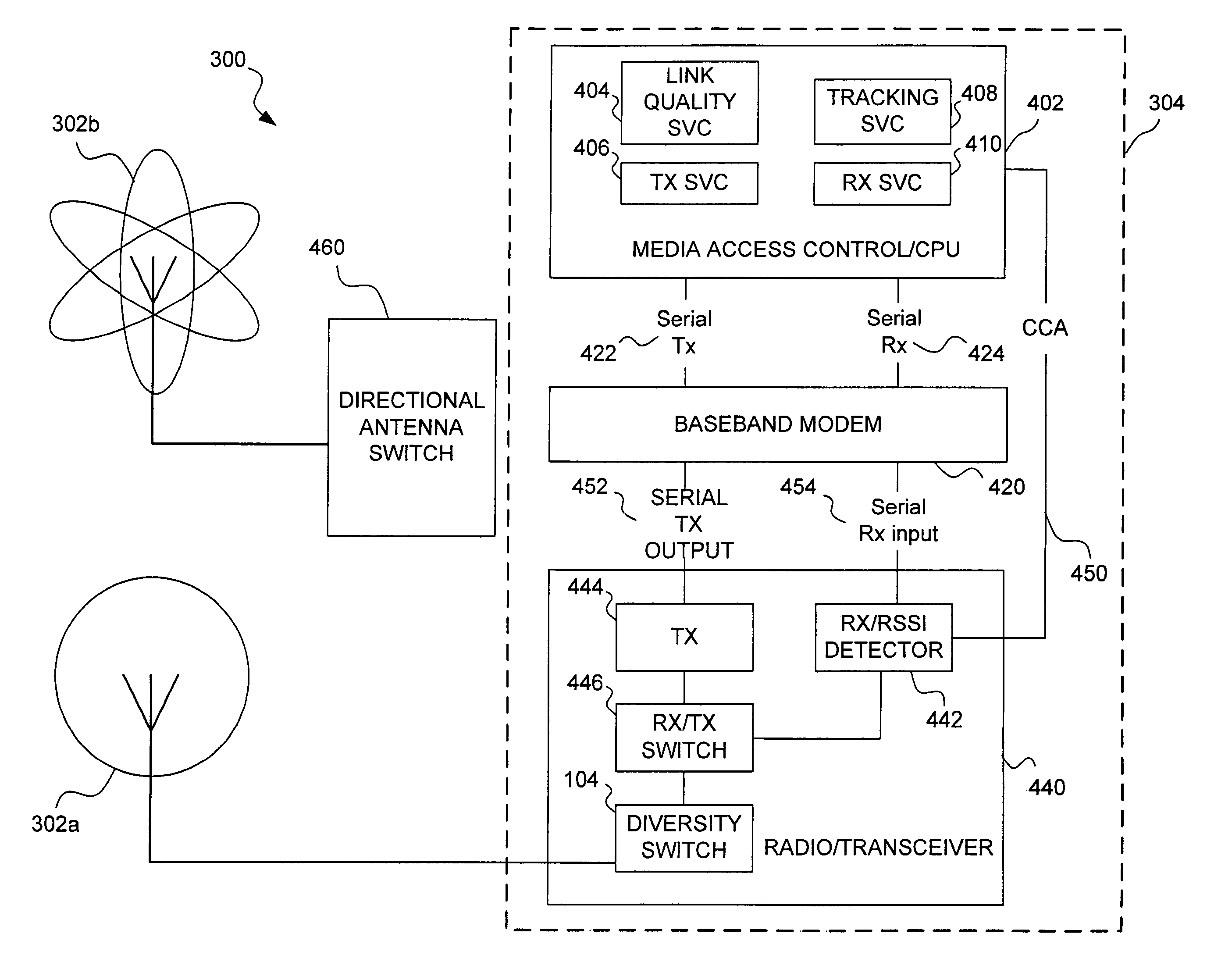
The present invention provides a wireless network that supports high-bandwidth client applications without the cost or complexity of dedicated antennas for each client. It includes an omnidirectional antenna and a directable antenna that can selectively provide coverage to clients in different directions. By automatically identifying the preferred direction in which to direct the antenna, the access point can communicate with clients at a faster rate, and the client can immediately take advantage of the improved gain to transmit to the access point at a higher communication rate. The omnidirectional antenna can transmit and receive signals in multiple directions, while the directable antenna can communicate with clients in a specific direction. The access point can also communicate with clients in different directions simultaneously, improving the overall communication rate. The invention provides an optimal directional space for each client, based on the characteristics of the transmission and the wireless network. Overall, the invention enhances wireless network communication speed and efficiency.

Problems solved by technology

In particular, conveying streaming video over a wireless network link can easily overburden the wireless connection by exceeding its throughput capability.
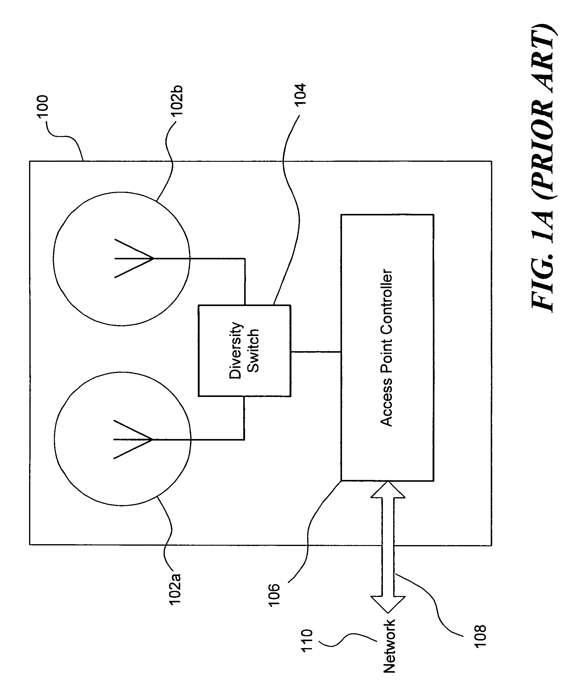
Thus, switching between antennae—even antennae incorporated in or attached to a relatively compact device—can appreciably affect communication between an access point and a client.
Although an access point is able to reliably communicate with a more distant or a less optimally situated distant client by switching to a lower communication rate, data communication at the lower data rate may be unsatisfactory for the intended application.
Furthermore, communication of a fixed amount of data at a low rate consumes more channel time, resulting in less time to communicate with other clients on the network.
Multiple-radio transceiver access points with directable antennae unfortunately present a number of disadvantages.
First, equipping the access point with multiple transceivers and the logic needed to control those transceivers understandably makes the access point much more costly to manufacture.
As a result, multiple-radio transceiver access points may be too costly for in-home wireless networks or even for small business wireless networks.
Second, for reasons previously described with regard to signals being obstructed by or reflected by objects in the communication area, setting up the access point to properly direct the directable antennae may be difficult.
Similarly, because obstacles move, or the client computers may be moved, and due to other factors, it may be inconvenient or impractical to adjust the directing of the antennae to a fixed orientation.
Third, although facilitating faster communication with some clients, using directable antennae may result in a limited coverage area that does not allow some clients to communicate with the access point.
Fourth, using directable antennae with a multiple-radio transceiver access point can create overhead problems that may undermine the benefit of the multiple-radio transceiver access point.
Fifth, providing directable antennae trained on each of a number of clients may be a waste of resources.
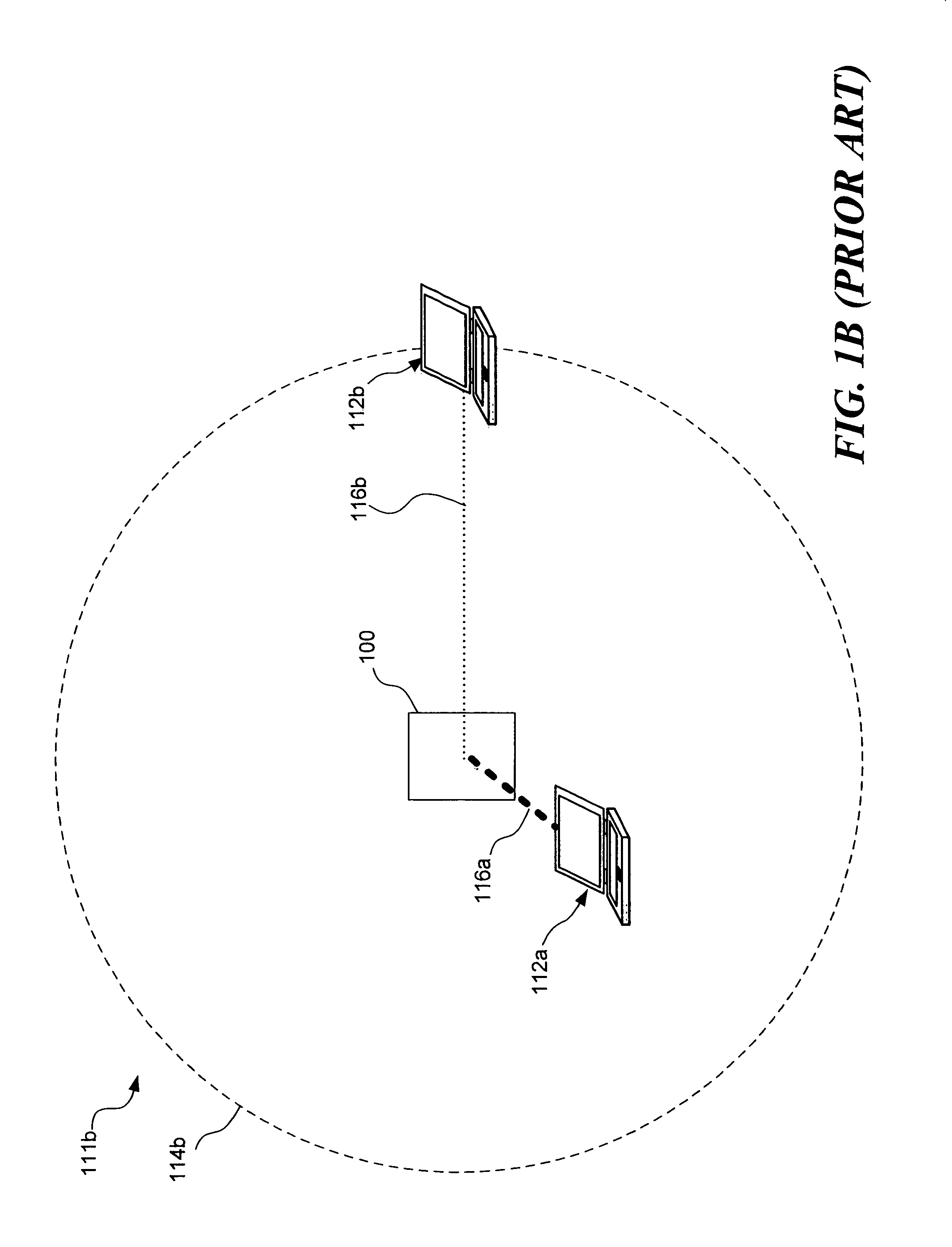
On the other hand, if client 112b is casually accessing Internet web pages or sending e-mail, the higher data communication rate facilitated by the directable antenna would be unnecessary and could be viewed as a waste of hardware resources and processing overhead.

Method used


Image

  • Multi-access system and method using multi-sectored antenna
  • Multi-access system and method using multi-sectored antenna
  • Multi-access system and method using multi-sectored antenna

Examples


Embodiment Construction

General Operation of an Access Point According to an Embodiment of the Invention

[0042]FIG. 2 illustrates a functional view of the operation of an access point according to an embodiment of the present invention. Wireless network 200 includes an access point 210 having both omnidirectional and directable antennae. A network space defined by the communication range of the omnidirectional antenna is represented by a dotted line 220. A plurality of directional communication spaces of the directable antenna are represented by dash lines 230. The directional communication spaces at least partially overlap the network space defined by dotted line 220.

[0043]The directable antenna is directable among the plurality of directional ranges defined by dash lines 230. Thus, in contrast to some previously available access points having multiple radio transceivers each coupled with a directable antenna covering a particular communication range, the directable antenna used in this embodiment of the p...


PUM


Abstract

A wireless access point is equipped with both an omnidirectional antenna and a directable antenna that can be selectively directed to any of a plurality of directional spaces overlapping the network space served by the omnidirectional antenna. The directable antenna is directed to an optimal directional space for a client when the access point is communicating with the client at a high data rate. The access point can intermittently exchange information with other clients using the omnidirectional antenna. The omnidirectional antenna enables broadcast signals to be transmitted to any client in the entire network space, but at a lower data rate. A preferred data rate and an optimal client directional space are re-determined periodically or as necessary based on parameters such as the data rate, signal strength, and rate of success in communicating data.

Description

FIELD OF THE INVENTION[0001]The present invention generally pertains to the use of a multi-sector antenna in a wireless computer network, and more specifically, to a method and system for improving communication efficiency in a wireless computer network by selecting a direction for transmitting and receiving signals with such an antenna so as to improve the signal strength and / or signal to noise ratio of wireless signals.BACKGROUND OF THE INVENTION[0002]The demand for computers to be able to communicate with each other and share resources continues to increase. Wireless networking fulfills this demand without the time, cost, and inconvenience of running network cables. Furthermore, as is well understood, wireless networking affords much greater flexibility to computer users by enabling them to access a network without being tethered to a network connection.[0003]While wireless computer networking has grown in popularity, at the same time, applications that require increasingly more ...

Claims


Application Information

Patent Timeline
Patent Type & Authority Patents(United States)
IPC IPC(8): H04B7/00
CPCH04B7/061
Inventor KING, WAYNE G.RANTA, CRAIG STEVENGIAIMO, III, EDWARD C.BRENNAN, JAMES
Owner MICROSOFT TECH LICENSING LLC
Learn More