
Time of flight mass spectrometer

a mass spectrometer and time-of-flight technology, applied in mass spectrometers, separation processes, dispersed particle separation, etc., can solve the problems of inability to carry out analysis with adequate accuracy, difficult to incorporate a long straight path in tof-ms, etc., to achieve convenient operation, reduce the effect of mass spectrum and simple configuration

Inactive Publication Date: 2008-04-08
SHIMADZU CORP
View PDF12 Cites 24 Cited by
  • Summary
  • Abstract
  • Description
  • Claims
  • Application Information

AI Technical Summary

Benefits of technology

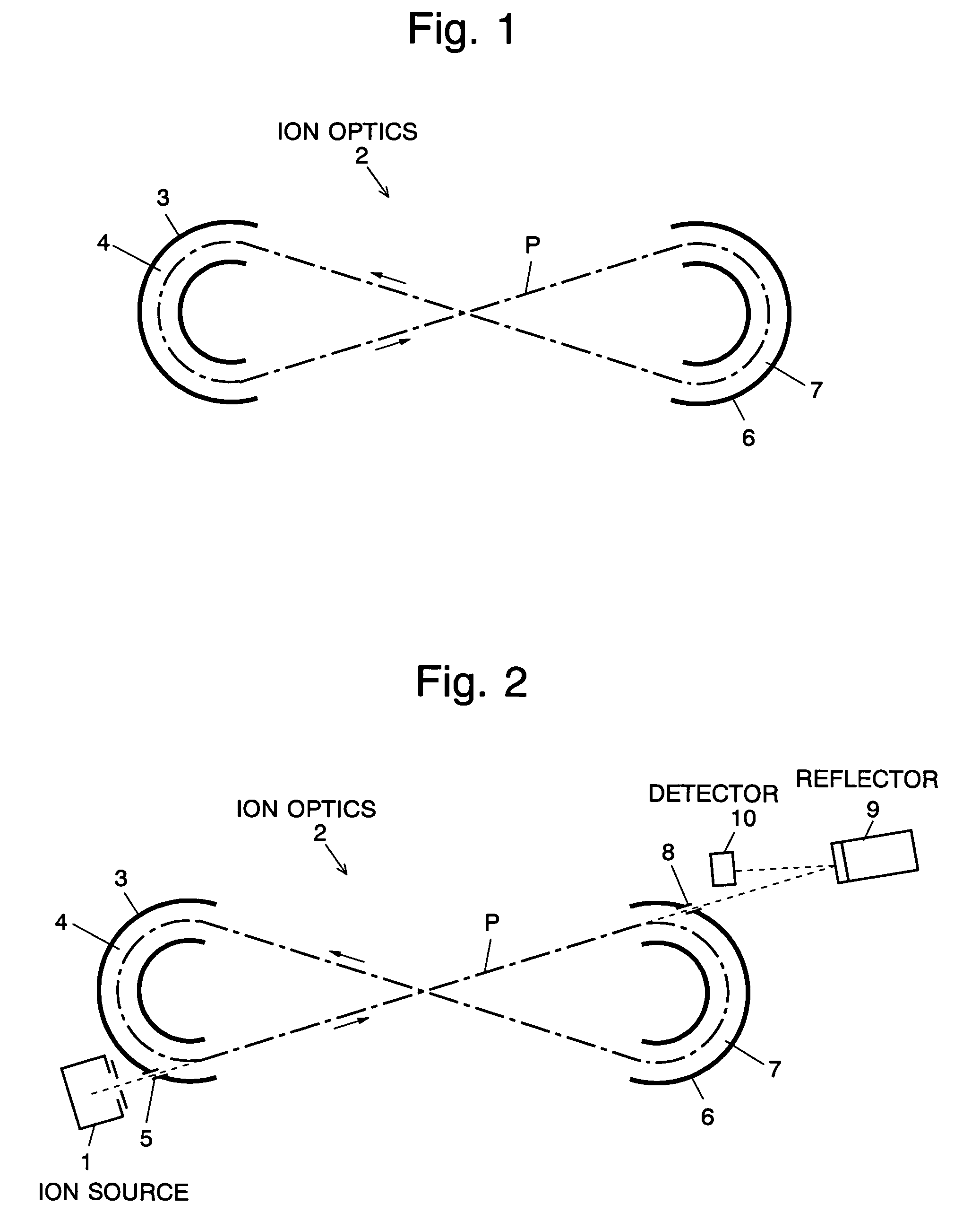
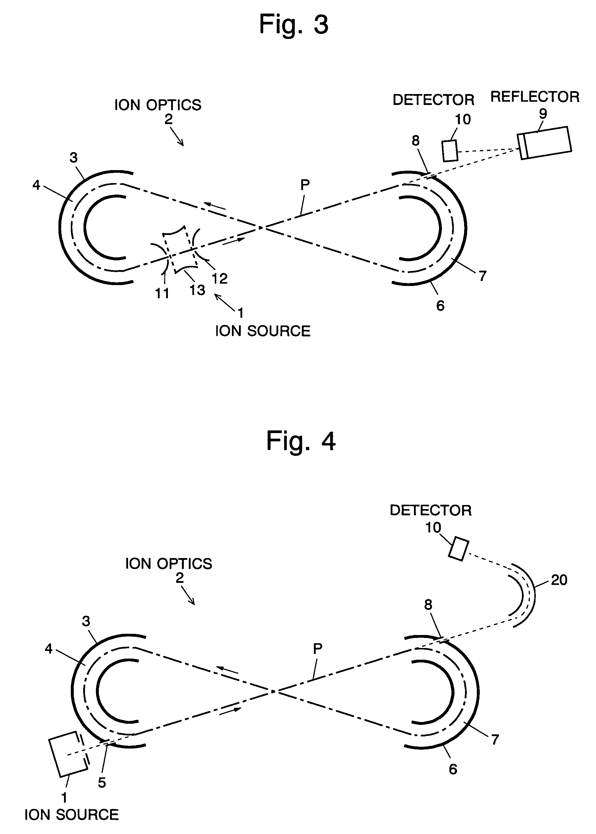
[0016]As mentioned earlier, the configuration of the electric field generator is to be rather limited in order to achieve the time-focusing within the multi-turn track, whereas, according to the TOF-MS of the present invention, the configuration of the multi-turn track has a large degree of freedom and the time-focusing can be achieved throughout the overall system from the ion source to the ion detector by a relatively simple configuration, i.e. by merely adding the compensating means to a portion out of the multi-turn track. Accordingly, the ions having the same mass number reach the detector at approximately the same time, thereby yielding a preferable mass spectrum and improving the accuracy of qualitative analysis and quantitative analysis based on the spectrum.

Problems solved by technology

In many cases, however, it is difficult to incorporate a long straight path in a TOF-MS due to the limited overall size, so that various measures have been taken to effectively lengthen the flight length.
Thus, the analysis cannot always be carried out with adequate accuracy.

Method used


Image

  • Time of flight mass spectrometer
  • Time of flight mass spectrometer
  • Time of flight mass spectrometer

Examples


Embodiment Construction

[0022]Firstly, the method of expressing an ion path in the following description is specified. The same expressions as in Patent Document 1 are used in order to clarify the contrast with the configuration described therein. Specifically, it is assumed that the ions are injected thorough an injection plane, then carried by an arbitrary type of ion optics including sector-shaped electric fields and finally ejected through an ejection plane. Also, the ion that has a specific amount of energy and a specific mass number and flies along the central path is defined as a reference ion. If an ion has left the injection plane with its position, flight direction (or angle) and energy level being initially shifted from those of the reference ion, the ion will have spatial and temporal divergences from the reference ion flying along the central path when it reaches the ejection plane. The divergences can be approximated by the following linear equations according to a well-known theory of ion op...


PUM


Abstract

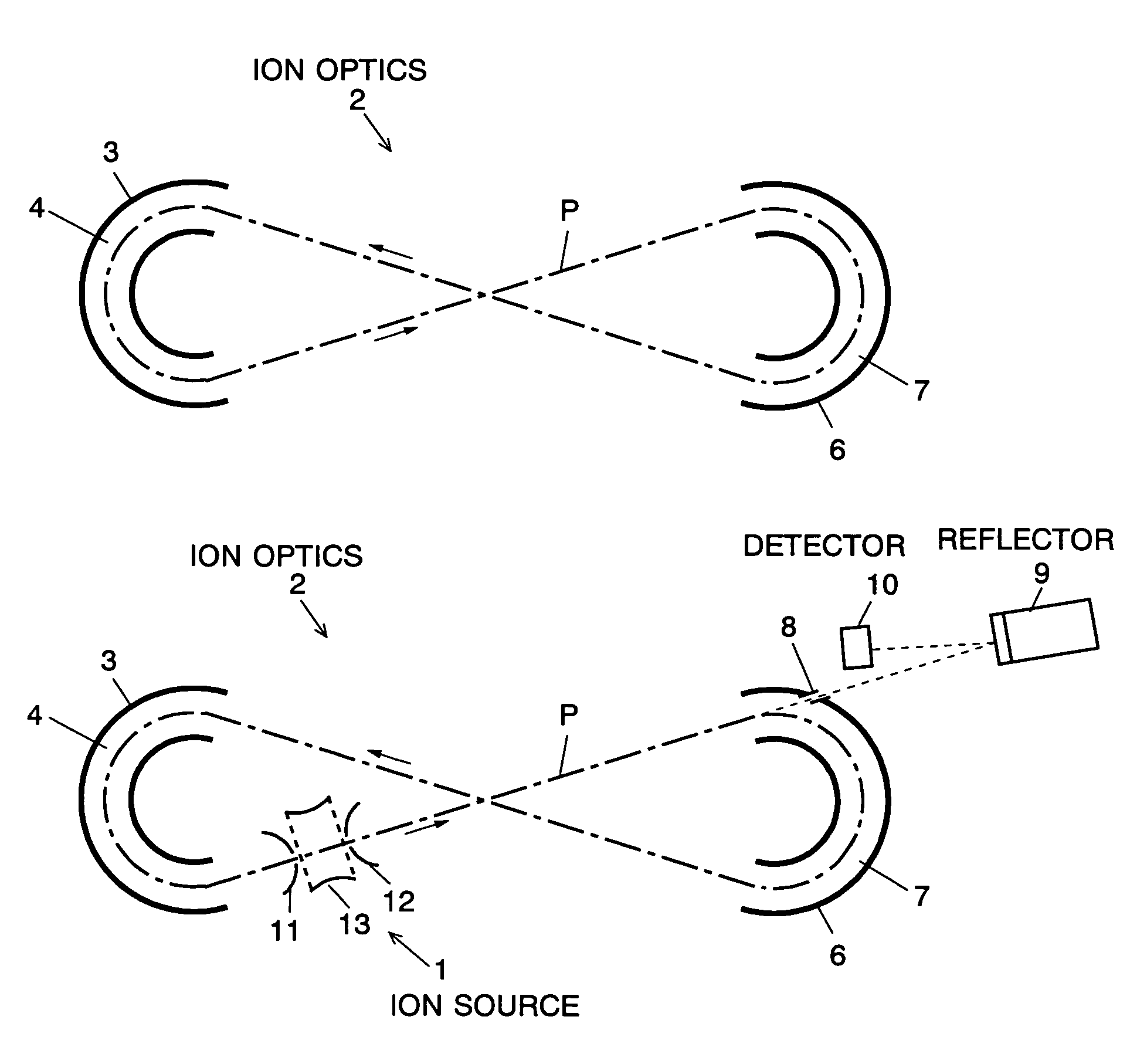
The present invention provides a time of flight mass spectrometer having an ion optics forming a multi-turn track, which is capable of time-focusing the ions while allowing the multi-turn track to be configured in an unlimited and highly variable manner. In a specific form of the invention, a reflector 9 is provided on the flight path between the position where the ions leave the loop orbit P and the ion detector 10 located outside the loop orbit P, and the condition of the electric field generated by the reflector 9 is appropriately determined. Thus, even if the ions cannot be well time-focused by the ion optics 2 creating the sector-shaped electric fields 4 and 7, it is possible to compensate the time-focusing performance with the reflector 9 to achieve a good performance of time-focusing of the ion throughout the overall system wherein the ions leave the ion source 1 and finally reach the ion detector 10. Thereby, the ions can reach the ion detector 10 at approximately the same time even if the ions having the same mass number have different levels of energy at the moment they leave the ion source 1.

Description

[0001]The present invention relates to a time of flight mass spectrometer having a flight space in which ions to be analyzed repeatedly fly substantially the same loop orbit or a reciprocal path.BACKGROUND OF THE INVENTION[0002]In a time of flight mass spectrometer (TOF-MS), ions accelerated by an electric field are injected into a flight space where no electric field or magnetic field is present. The ions are separated by their mass numbers according to the flight time until they reach a detector and are detected thereby. Since the difference of the lengths of flight time of two ions having different mass numbers is larger as the flight path is longer, it is preferable to design the flight path as long as possible in order to enhance the mass number resolution of a TOF-MS.[0003]In many cases, however, it is difficult to incorporate a long straight path in a TOF-MS due to the limited overall size, so that various measures have been taken to effectively lengthen the flight length. In...

Claims


Application Information

Patent Timeline
Patent Type & Authority Patents(United States)
IPC IPC(8): H01J49/40
CPCH01J49/282H01J49/408
Inventor YAMAGUCHI, SHINICHI
Owner SHIMADZU CORP
Learn More