


Quick Research
Generate reliable direction feasibility study reports for your R&D in just a few steps.

Technical Q&A
Discover and master advanced knowledge NOW. Basics, ideas, possibilities, all at once.

Find Solutions
As an expert in R&D theories, this can generate solutions to your technical problems instantly.

Evaluate Feasibility
Analyze your overall solution with one click, know your potential R&D risks in advance.

Monitor Landscape
Get weekly tech updates, stay abreast of the latest tech innovations and key insights.
Bearing for a wheel of vehicle
- Summary
- Abstract
- Description
- Claims
- Application Information
AI Technical Summary
Benefits of technology
Problems solved by technology
Method used
Image

Examples
first embodiment
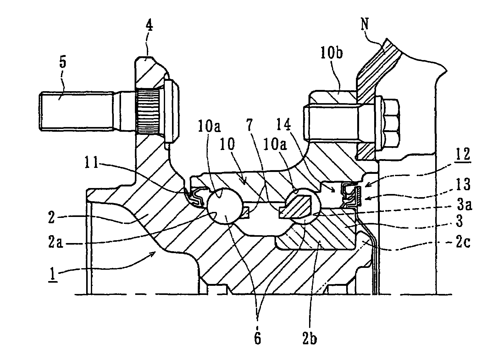
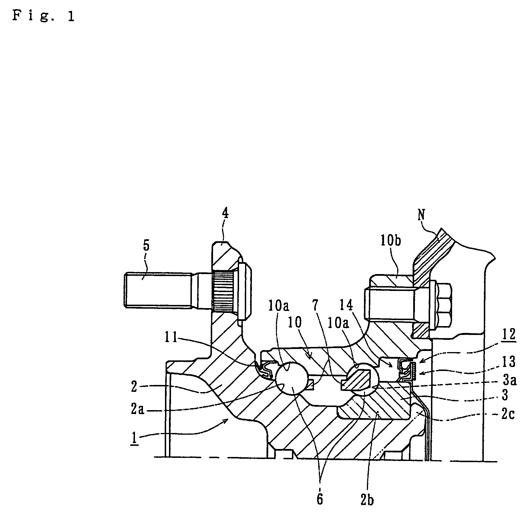
[0040]FIG. 1 is a longitudinal-section view of a vehicle wheel bearing of the present invention. FIG. 2 is a partially enlarged longitudinal-section view of FIG. 1. In the description of the present invention, a side of a bearing positioned outward of a vehicle when it is mounted on a vehicle is referred to as “outboard” side (the left side in a drawing), and a side inward of a vehicle is referred to as “inboard” side (the right side in a drawing).
[0041]The bearing of FIG. 1 has an inner member 1, an outer member 10, and double row rolling elements 6 and 6 held between the inner and outer members 1 and 10. The inner member 1 includes a wheel hub 2 and a separate inner ring 3 fitted on the outer circumferential surface of the wheel hub 2. The wheel hub 2 is formed integrally with a wheel mounting flange 4 for mounting a wheel (not shown). Hub bolts 5 secure the wheel and are equidistantly arranged along the periphery of the flange 4. The inner ring 3 is press-fitted on a stepped port...
second embodiment
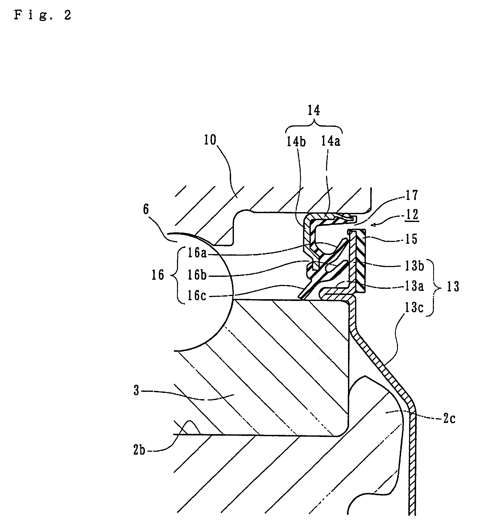
[0051]According to this second embodiment, since the first sealing plate 19 is formed as a disk and integrally secured to the end face of the inner ring 3 by plastically deforming the end of the stepped portion 2b of the wheel hub 2, no rain water or dusts penetrates into the bearing from ambient. The fitted surfaces and the inner ring 3 are not exposed to the ambient. Accordingly, the delayed fracture of the inner ring 3 can be prevented.
[0052]A third embodiment of the vehicle wheel bearing is shown in a partially enlarged view of FIG. 4. Since difference of this embodiment from the second embodiment (FIG. 3) only resides in the structure of the first sealing plate and the caulked portion, the same numerals are used as those used in the previous embodiments for designating the same structural elements.
[0053]Similarly to the first and second embodiments, the second sealing plate 14 of a sealing device 12′ on the inboard side of this embodiment is mounted on the outer member 10. A fi...
fourth embodiment
[0055]the vehicle wheel bearing is shown in longitudinal cross-section view in FIG. 5. FIG. 6(a) is a partially enlarged view of FIG. 5. Since difference of this embodiment from the previous embodiments only resides in the structure of the sealing device on the inboard side, the same numerals are used as those used in the previous embodiments to designate the same structural elements.
[0056]As shown in the enlarged view of FIG. 6(a), the sealing device 21 of inboard side has first and second annular sealing plates 23 and 24 mounted on the inner ring 3 and the outer member 10, respectively. The first sealing plate 23 has a cylindrical portion 23a and a radially extending portion 23b extending radially outward from the end of the cylindrical portion 23a to form a substantially “L” shaped configuration. The first sealing plate 23 is formed by press working of ferromagnetic sheet e.g. ferrite-stainless steel sheet (e.g. JIS SUS 430 etc.) or preserved cold rolled steel sheet (e.g. JIS SPC...
PUM
 Abstract
Description
Claims
Application Information
 - R&D Engineer
- R&D Manager
- IP Professional
- Industry Leading Data Capabilities
- Powerful AI technology
- Patent DNA Extraction
Browse by: Latest US Patents, China's latest patents, Technical Efficacy Thesaurus, Application Domain, Technology Topic, Popular Technical Reports.
© 2024 PatSnap. All rights reserved.Legal|Privacy policy|Modern Slavery Act Transparency Statement|Sitemap|About US| Contact US: help@patsnap.com