Cutting tool assembly for milling a rail top

Active Publication Date: 2017-09-07
KENNAMETAL INC
View PDF14 Cites 4 Cited by
  • Summary
  • Abstract
  • Description
  • Claims
  • Application Information

AI Technical Summary

Benefits of technology

The patent addresses the problem of providing a cutting tool that can smoothly and efficiently mill a rail form, while also maintaining consistent tool pressure and improving the lifespan of the tool. The solution involves helically mounting multiple types of cutting inserts on the tool.

Problems solved by technology

As a result, conventional cutting tools experience increased tool pressure, shortened tool life, and less efficiency during the milling of the rail form.

Method used


Image

  • Cutting tool assembly for milling a rail top
  • Cutting tool assembly for milling a rail top
  • Cutting tool assembly for milling a rail top

Examples


Embodiment Construction

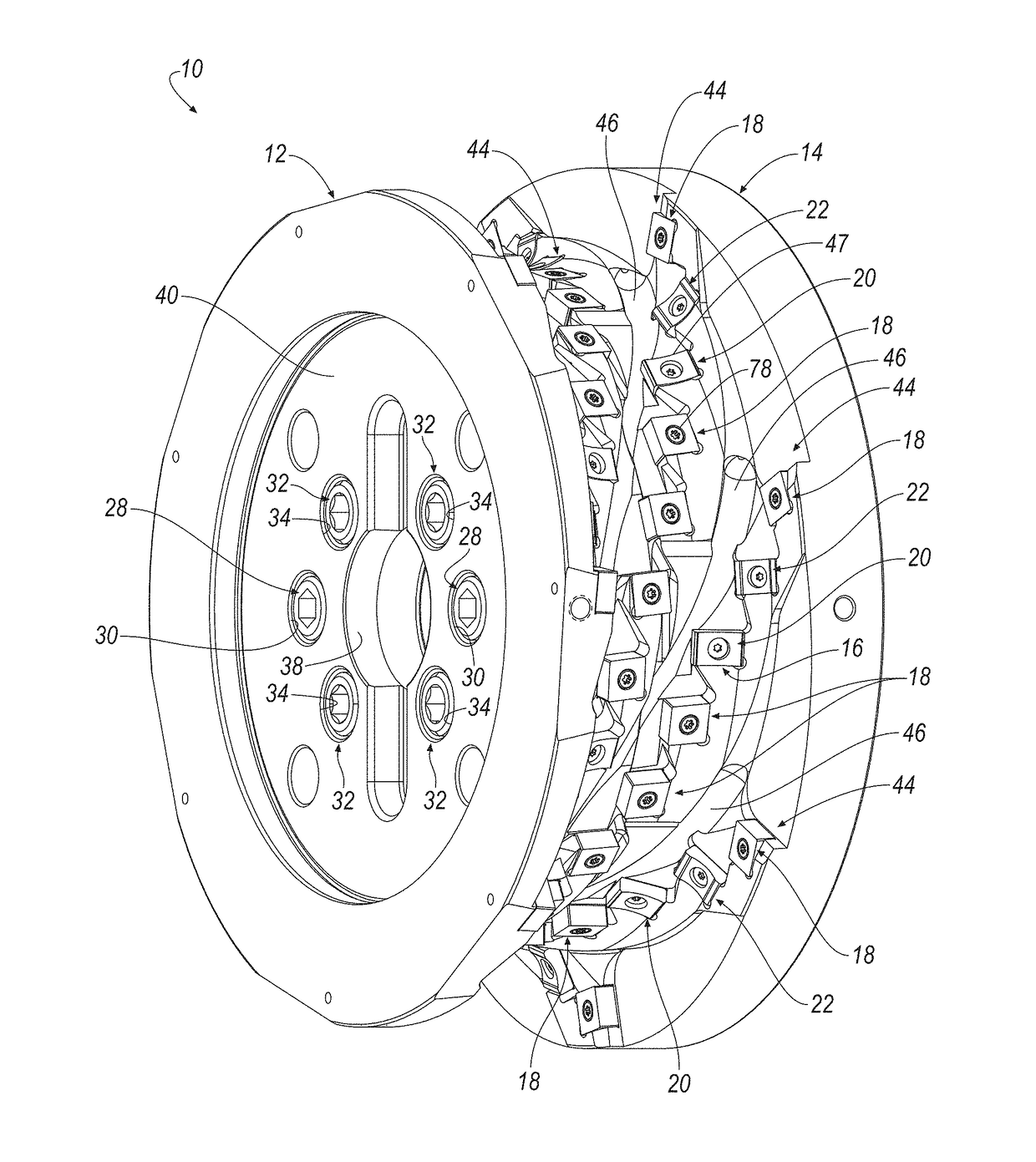
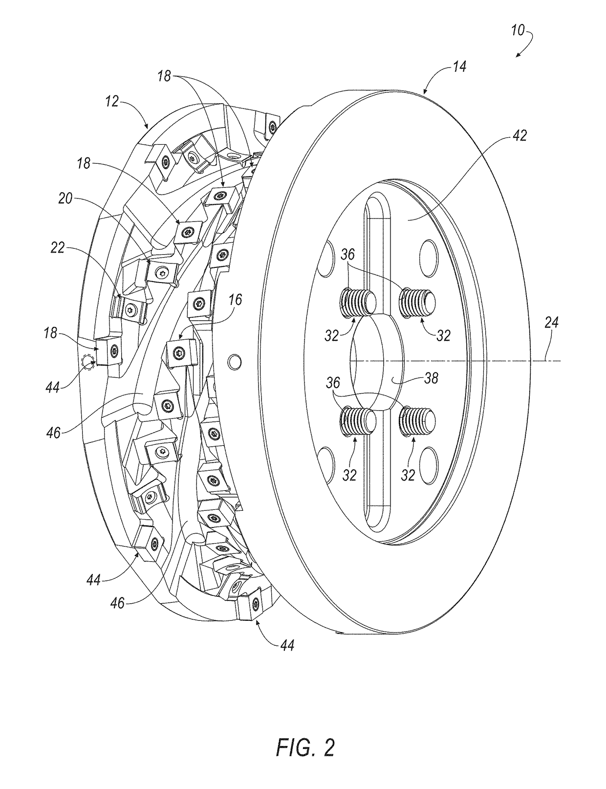
[0024]Referring now to FIGS. 1-5, a cutting tool assembly 10, for example, a form mill for milling a rail top 200, includes a first section 12 and a second section 14 mounted to the first section 12. In general, each section 12, 14 includes a plurality of insert-receiving pockets 16 for receiving a plurality of different types of cutting inserts 18, 20, 22. As seen in FIGS. 3 and 4, each section 12, 14 has a width, W1, W2, of about one-half (½) of a total width, W, of the cutting tool assembly 10 (FIG. 5).

[0025]One section 12, 14, for example, the first section 12 may include a dowel pin 23 and a drive key 25 for ensuring that the first section 12 is properly mounted to the second section 14 (FIG. 3). The cutting tool assembly 10 rotates about a central, rotational axis 24, and also has a longitudinal axis 26 that is substantially perpendicular to the central, rotational axis 24. The first section 12 is secured to the second section 14 by inserting a threaded fastener 28 through an ...


PUM


Abstract

A cutting tool assembly for milling a rail top, includes a first section and a second section mounted to the first section. Each section includes a plurality of insert-receiving pockets for receiving a plurality of different types of cutting inserts. The plurality of different types of cutting inserts are arranged in a plurality of helical teeth that may be separated by a helical chip flute. In one embodiment, a first type of cutting insert is formed with a radius, R, a second type of cutting insert is formed with a radius, R1, and a third type of cutting insert is formed with a radius, R2, to perform a milling operation on three different areas of the rail top.

Description

BACKGROUND OF THE INVENTION[0001]Field of the Invention[0002]The invention relates to a cutting tool. More particularly, the invention pertains to a cutting tool for milling a rail top with a plurality of different types of cutting inserts helically mounted on the cutting tool.[0003]Description of Related Art[0004]Conventional cutting tools for milling a rail top consists of random spacing of the cutting inserts and a square pocket design for the chip flutes. As a result, conventional cutting tools experience increased tool pressure, shortened tool life, and less efficiency during the milling of the rail form. Thus, there is a need to provide a cutting tool that provides smoother, efficient milling of the rail form, while providing consistent tool pressure, thereby improving tool life.SUMMARY OF THE INVENTION[0005]The problem of providing a cutting tool with smoother, efficient milling of a rail form, while providing consistent tool pressure and improving tool life is solved by heli...

Claims


Application Information

Patent Timeline
IPC IPC(8): B23C5/14B23C3/00
CPCB23C5/14B23C3/005B23C2210/242B23C2215/32B23C2210/287B23C2210/325B23C2210/40B23C2210/285B23C5/02B23C5/12B23C2200/123B23C2200/203B23C2200/367B23C2210/244E01B31/13B23C5/202
Inventor SAFFELS, MICHAEL DAVIDWILLIAMS, ELVIN CHARLESROSENBAUM, FLOYD SAMUEL
Owner KENNAMETAL INC
Why Eureka
Try Eureka