Electric bed front motor drive structure

Active Publication Date: 2014-05-08
KEESON TECH CORP LTD
View PDF4 Cites 3 Cited by
  • Summary
  • Abstract
  • Description
  • Claims
  • Application Information

AI Technical Summary

Benefits of technology

The invention is an electric bed front motor structure that improves its driving structure to overcome the traditional connection structure defects. It aims to protect the bed board and motor, improve the bed's life, and reduce production costs. The structure includes an upper frame, lower frame, and front motor with a drive rod. The upper frame has guiding mechanisms, side bars, and guiding rails. The front motor bracket has a curved bracket and guide wheel or slider. The bottom edge of the linear bearing assembly and the base are connected. The structure reduces stress and strain on the bed board and motor, improving its lifespan and reducing production costs.

Problems solved by technology

The traditional connection structure has some flaws especially when dealing with super obese users.
Because the bedboard is mostly wood material having softer characteristics than metal, the bedplate lifting force of the drive rod points are initially highly concentrated in the bed board and the bracket screws are easy to dislodge and bed board damage may occur, which affects the service life of the electric bed.
Another traditional electric bed flaw is because of space limitations.
The front motor drive head backboard has a shorter lever arm, and its carrying of the motor load makes it easy to damage and also overload the front motor.
If using a larger load motor, the production costs of the electric bed are increased as some larger load motors are not mass-produced.
High initial stress concentration during initial rising from the prone position to the raised position could lead to pulling out of screws, overloading of a motor, or jerky movement for a user on the bed.

Method used


Image

  • Electric bed front motor drive structure
  • Electric bed front motor drive structure
  • Electric bed front motor drive structure

Examples


Embodiment Construction

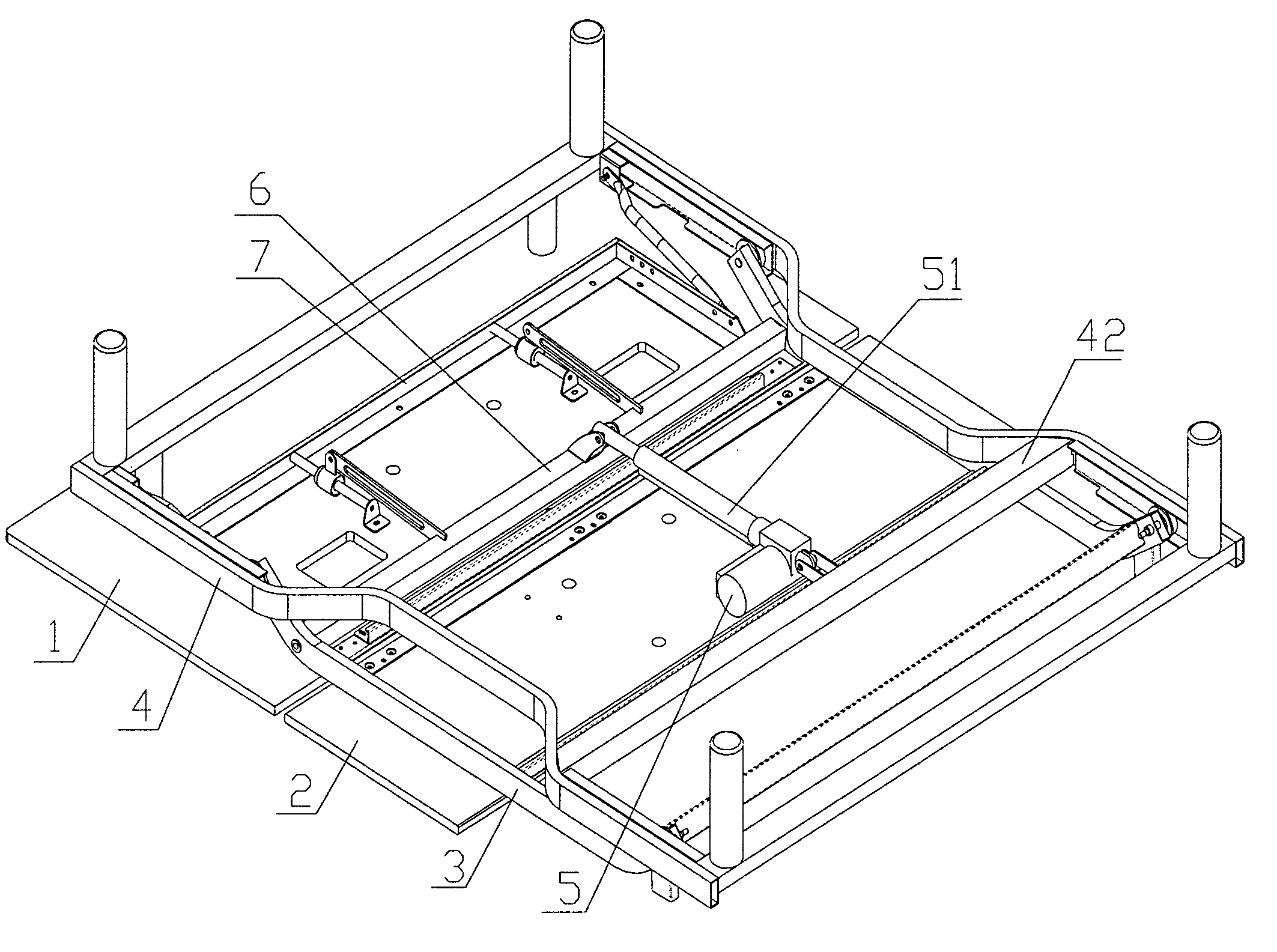
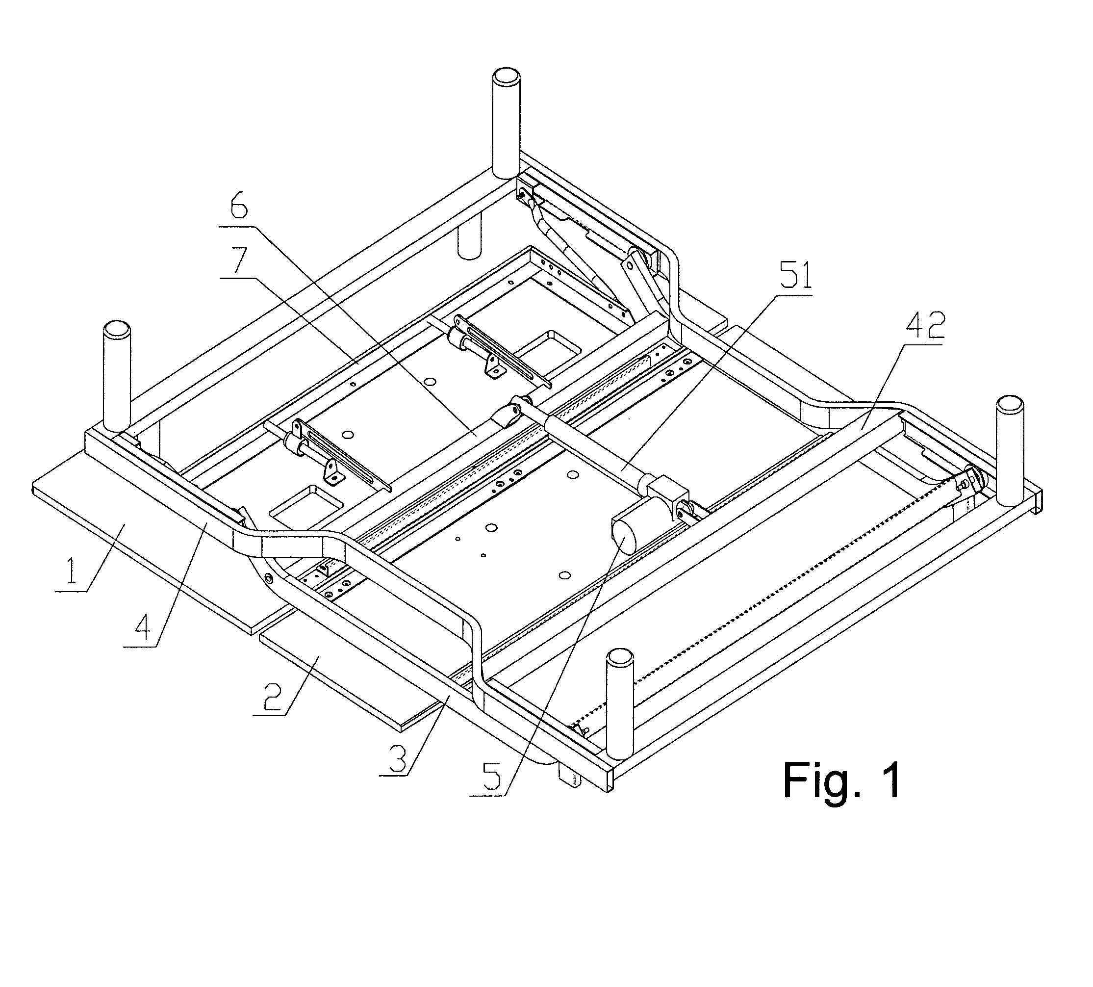
[0045]As shown in FIGS. 1 to 4, the front motor driving structure of the present invention electric bed comprises: a middle bedboard 2 that is fixed to the upper frame and hinged to a headback bedboard 1; a front motor 5; an upper frame 3, a lower frame 4, and a drive rod 51 of the front motor 5. The user sits on the middle fixed bedboard 2 and in the middle fixed bed board 2 can be called a seat board. The user head and back are supported by the headback bedboard 1.

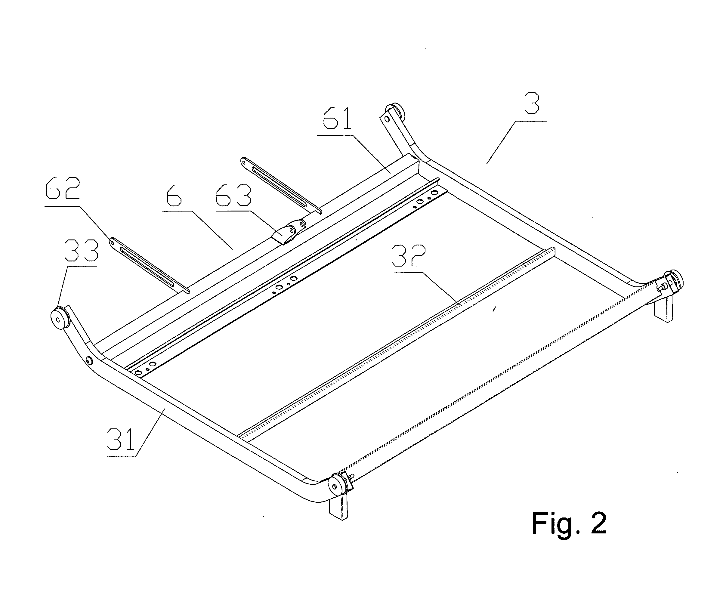
[0046]The upper frame 3 comprises two side bars 31, two horizontal bars 32 and four guiding mechanism 33. The two side bars 31 are arranged parallel at an interval with two ends bent down. The two horizontal bars 32 are parallel with each other and also set in between two sidebars 31. As described, four guide mechanisms 33 are between two sides of the two sidebars 33. Two horizontal bars 32 are set in the bottom of the fixed bed board 2. The above upper frame 3 has one end extending to the head back portion 1 bottom. The...


PUM


Abstract

The invention discloses an electric bed front motor drive structure. The structure of the drive head back bed board is connected to the fixed bed board. The top frame is set beneath the fixed bed board. the upper and lower frame are connected by guiding mechanism and rail movements. The bottom bedframe has intermediate connecting rods. The intermediate connecting rod has a first bracket. The rotation of the motor bracket lever is hinged at one end of the upper frame between the two side rods. Two connecting rods is set on the rotating rod. Second bracket is located underneath the motor bracket lever. The linear bearing assembly's bottom edge, two sides and two bases are located at the head back portion of the bed board underside. The two linear bearing assemblies connect the bottom edge and two bases.

Description

[0001]This application is being filed within 12 months of the filing date of its parent application and accordingly claims Paris Convention priority from China patent applications 201220579701.1 and 201210437918.3 both filed Nov. 6, 2012 and both entitled Electric Bed Front Motor Drive Structure by same inventor Shan, Huafeng, the disclosure of which is incorporated herein by reference.FIELD OF THE INVENTION[0002]The invention relates to an electric bed front motor drive structure.DISCUSSION OF RELATED ART[0003]With increasing diet and lack of physical exercise, motorized electric beds are becoming more popular in America. The traditional electric bed has a bedboard made of multiple pieces of hinged bedboard such as the headback bedboard, the fixed bedplate, and the leg bedboard and foot bed board. The bedboard has a bottom framework connected to the lower frame and the upper frame. Setting the front and rear motor drives the bedpanels to achieve lift and meet body posture needs. A ...

Claims


Application Information

Patent Timeline
IPC IPC(8): A61G7/015
CPCA61G7/015A47C20/041A61G7/002A61G7/012A61G7/018A61G2203/42
Inventor SHAN, HUAFENG
Owner KEESON TECH CORP LTD
Why Eureka
Try Eureka