
Quantum key distribution system and method using regulated single-photon source

a quantum key and source interferometer technology, applied in the field of quantum key distribution systems and methods, can solve the problems of low parametric down-conversion efficiency, sensitive phase control of source interferometers, and low communication efficiency, and achieves simple practical realization and higher key creation efficiency

Inactive Publication Date: 2008-03-18
NIPPON TELEGRAPH & TELEPHONE CORP +1
View PDF5 Cites 22 Cited by
  • Summary
  • Abstract
  • Description
  • Claims
  • Application Information

AI Technical Summary

Benefits of technology

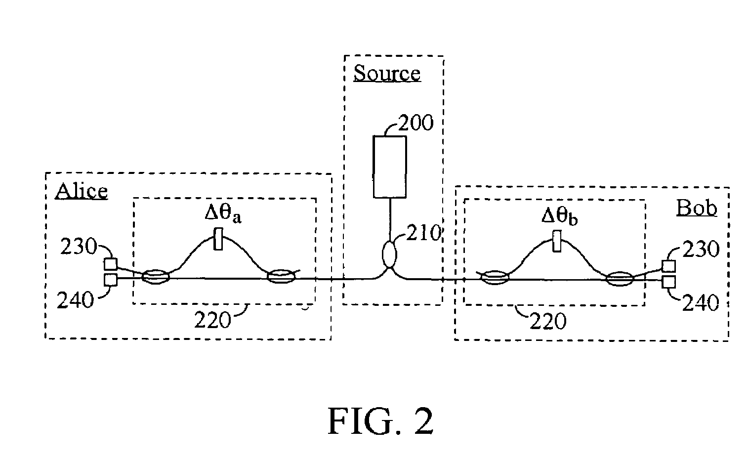
[0013]The present invention provides an improved technique for QKD that enjoys the advantages of energy-time entanglement approaches without the disadvantages associated with generating maximally-entangled photon pairs using parametric down-conversion. Surprisingly, the present inventors have discovered that QKD based on energy-time entanglement can be implemented without parametric down-conversion or other sources of maximally-entangled photon pairs. The technique of the invention enjoys a simpler practical realization as well as a higher key creation efficiency.

Problems solved by technology

A basic problem of cryptography, therefore, is how to initially establish a private key between Alice and Bob, and how to ensure that such a key distribution technique is secure against Eve.
This approach suffers from practical problems due to the fact that the polarization state of light changes in optical fibers due to randomly varying birefringence.
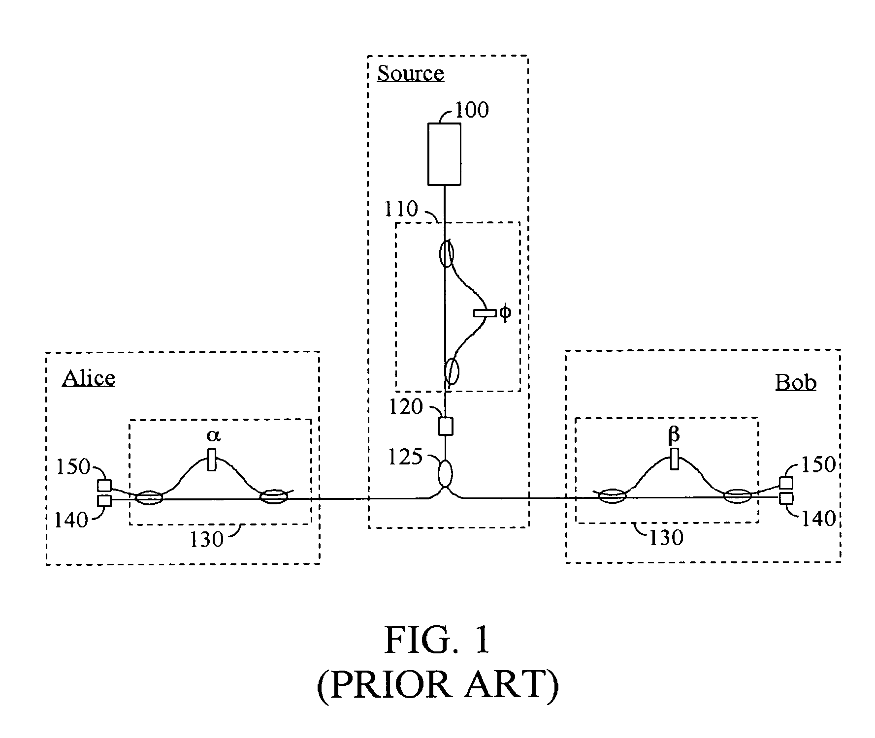
One disadvantage of this particular approach to QKD is its comparatively low communication efficiency due to the fact that the efficiency of the parametric down-conversion must be kept low.
Another disadvantage of the above approach to QKD is that it requires delicate phase control in the source interferometer.

Method used


Image

  • Quantum key distribution system and method using regulated single-photon source
  • Quantum key distribution system and method using regulated single-photon source
  • Quantum key distribution system and method using regulated single-photon source

Examples


Embodiment Construction

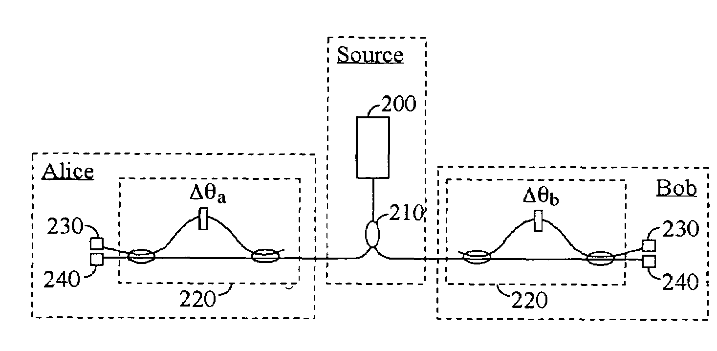
[0024]Embodiments of the invention provide novel energy-time entanglement QKD systems and methods. In contrast with prior energy-time entanglement QKD techniques whose photon source includes a pulsed laser, interferometer, parametric down-converter, and beam-splitter, according to embodiments of the present invention the entangled photons are generated by a regulated single-photon generator and a beam splitter. No parametric down-converter or interferometer is required at the source. The photon pairs are not generated in maximally entangled Bell states, as in the prior art. Surprisingly, the inventors have discovered that these photons can nevertheless be used to provide an QKD technique with a higher key creation efficiency than prior techniques using maximally-entangled photons generated by parametric down-conversion.

[0025]In contrast to previous approaches to energy-time entanglement QKD where all the generated photon pairs are separated and sent to different receivers, in a pref...


PUM


Abstract

A system and method for quantum key distribution uses a regulated single-photon source to sequentially generate a first photon and a second photon separated by a time interval Δt. The two photons are directed through a beam splitter that directs each photon to one of two transmission lines, which lead to two respective receivers. When one of the photons arrives at a receiver, it passes through an interferometer. One arm of the interferometer has a path length longer than the other arm by an amount equivalent to a photon time delay of Δt. The photon is then detected in one of three time slots by one of two single-photon detectors associated with each of the two interferometer outputs. Due to quantum-mechanical entanglement in phase and time between the two photons, the receivers can determine a secret quantum key bit value from their measurements of the time slots in which the photons arrived, or of the detectors where the photons arrived.

Description

CROSS-REFERENCE TO RELATED APPLICATIONS[0001]This application claims priority from US provisional patent application 60 / 431,151 filed Dec. 4, 2002.FIELD OF THE INVENTION[0002]This invention relates generally to systems and methods for quantum cryptography. More specifically, it relates to improved systems and methods for entanglement-based quantum key distribution.BACKGROUND OF THE INVENTION[0003]Cryptography is concerned with the secure transmission of private information between two parties (referred to conventionally as Alice and Bob). When a classical communication channel is used, there is always the possibility that a third party (referred to as Eve) may eavesdrop on the channel. Thus, techniques must be used to secure the privacy of the transmitted information. For example, in classical cryptography Alice typically uses a cryptographic key to encrypt the information prior to transmission over the channel to Bob, so that it remains secure even if the channel is public. In orde...

Claims


Application Information

Patent Timeline
Patent Type & Authority Patents(United States)
IPC IPC(8): H04L9/00H04L9/08H04L9/12
CPCH04L9/0858
Inventor INOUE, KYOWAKS, EDOYAMAMOTO, YOSHIHISA
Owner NIPPON TELEGRAPH & TELEPHONE CORP
Learn More