
Direct modulation of a power amplifier with adaptive digital predistortion

a direct modulation and power amplifier technology, applied in the field of digital wireless communications, can solve the problems of significant power efficiency decline, strong restriction on the implementation of rf transmitters, and extremely tight tolerances on the matching of two amplifier paths to achieve acceptable small out-of-band rejection

Inactive Publication Date: 2008-03-18
CAO WEIXUN
View PDF14 Cites 74 Cited by
  • Summary
  • Abstract
  • Description
  • Claims
  • Application Information

AI Technical Summary

Benefits of technology

[0014]The present invention pertains to a generic RF transmitter architecture using a switching-mode power amplifier to maximize the power efficiency and method therefor. According to one aspect of the present invention, RF transmitter systems employing the present invention can achieve both high power efficiency and high linearity for different modulation standards but be of low cost. The present invention may be advantageously used in the mobile devices and / or base stations (e.g., the third generation (3G) wireless communication systems and advanced satellite communication systems).
[0016]high power efficiency is obtained by using switching-mode RF amplifiers;
[0021]high performance linear modulation of RF signals with low output noise power, spurious levels and current consumption are achieved; and
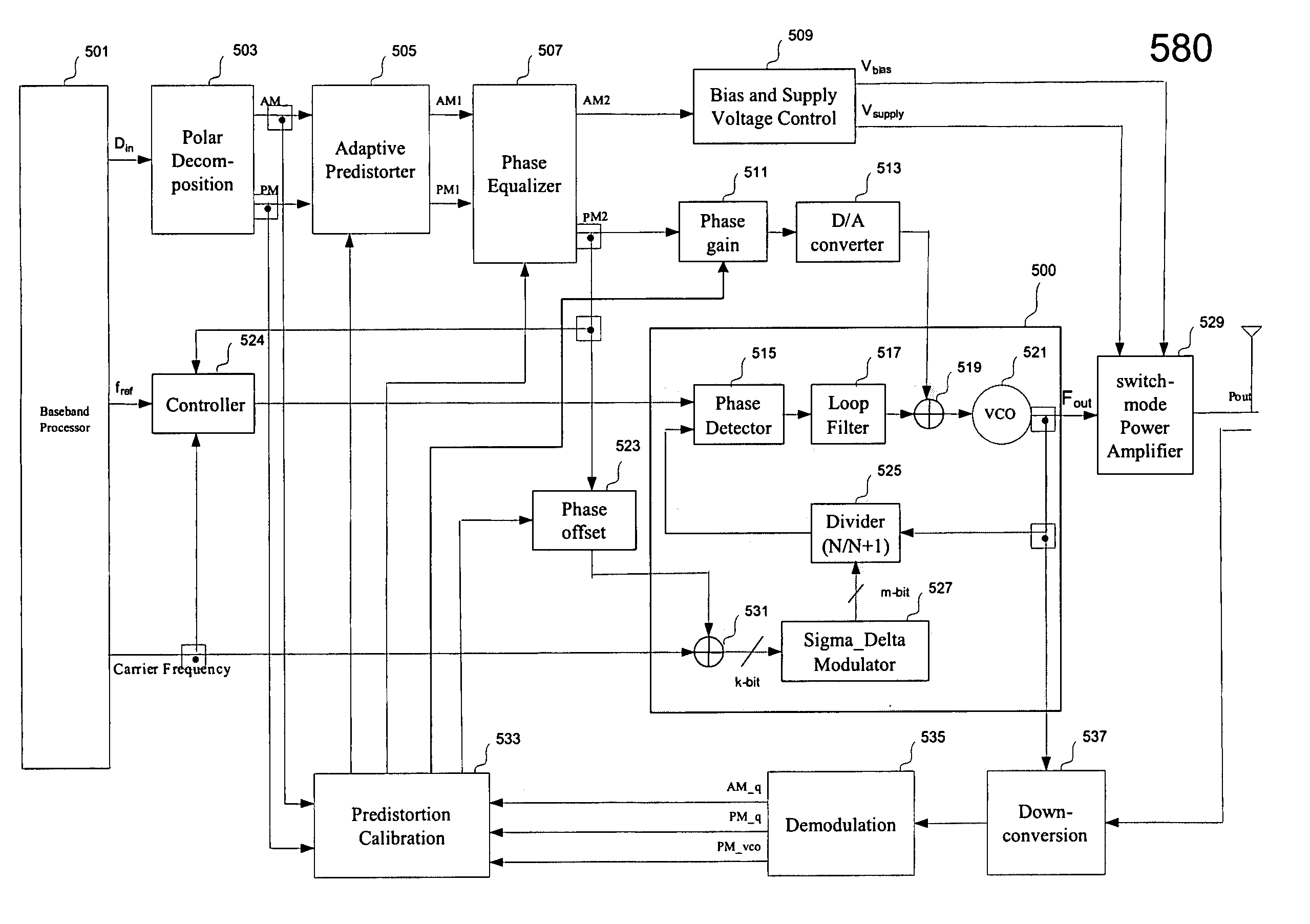
[0025]There are many features, benefits and advantages in the present invention. One of these is to provide a generic architecture that uses amplitude and phase information to directly modulate a switching-mode power amplifier with adaptive digital predistortion. The digital predistortion includes a demodulation feedback path to detect the amplitude and phase signals generated by the power amplifier and the voltage-controlled oscillator, and adaptively correct the non-linear effects of the switching-mode power amplifier and the voltage-controlled oscillator. The timing mismatch between the amplitude and phase signals is also adaptively compensated by using digital predistortion.
[0026]Another one of the features, benefits and advantages is to provide a wideband phase modulation architecture using the direct modulation of a VCO with a fractional-N frequency synthesizer. It eliminates the intermediate frequency (IF) up-conversion mixer and costly band pass filters for conventional transmitter chains. The VCO drift, temperature variations and other nonlinear effects of a power amplifier are compensated by using digital predistortion with adaptive phase offset and gain control techniques.

Problems solved by technology

The requirements of high linearity, high power efficiency and low cost result in a strong restriction on the implementation of a RF transmitter which must have both ultra-linearity and high power efficiency for constant and non-constant envelope modulation standards.
However, such an operation leads to a significant decrease in the power efficiency.
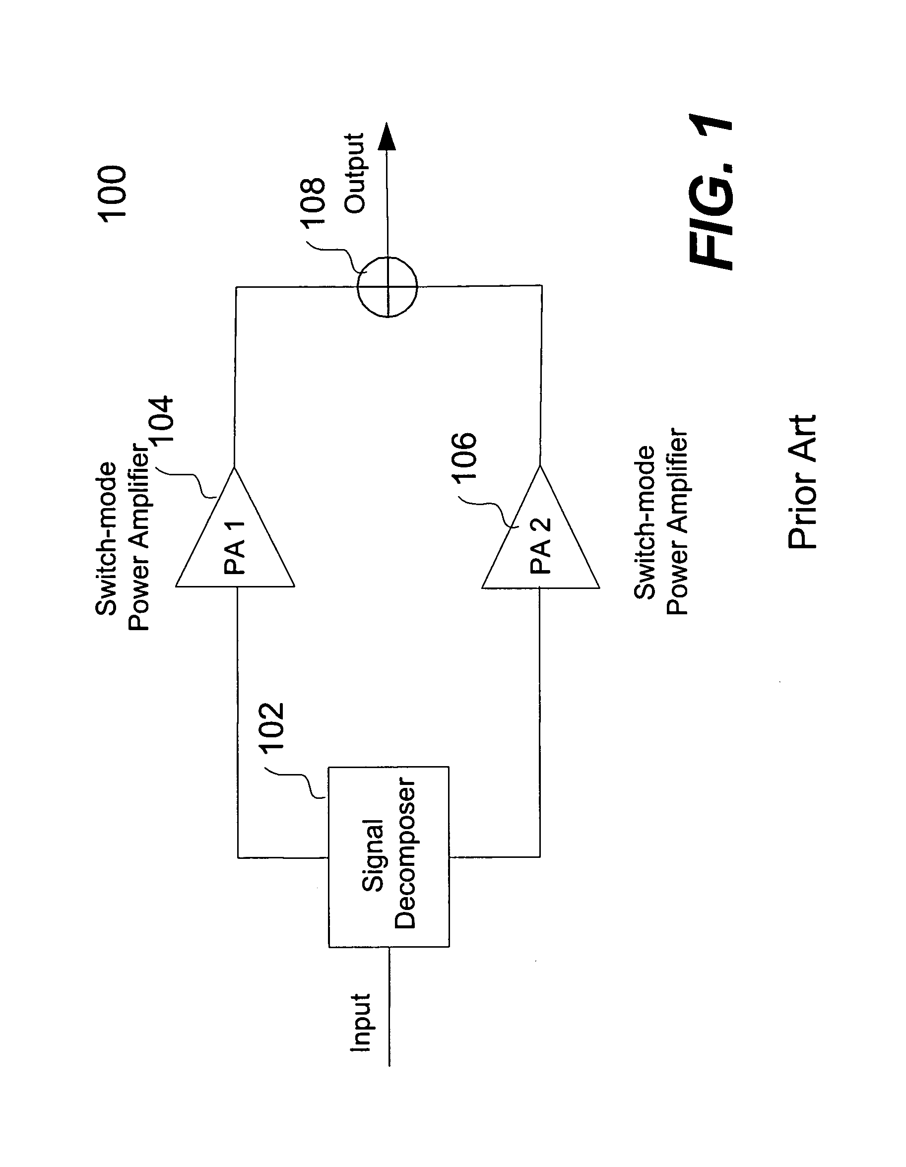
However, one of the disadvantages of this technique is the extremely tight tolerances on the matching of the two amplifier paths to achieve acceptable small out-of-band rejection.
Another one of the drawbacks encountered with this technique is that the output power combiner will introduce a significant loss of power efficiency.
This is difficult since the two paths include vastly different types of circuit elements, working at widely different frequencies.
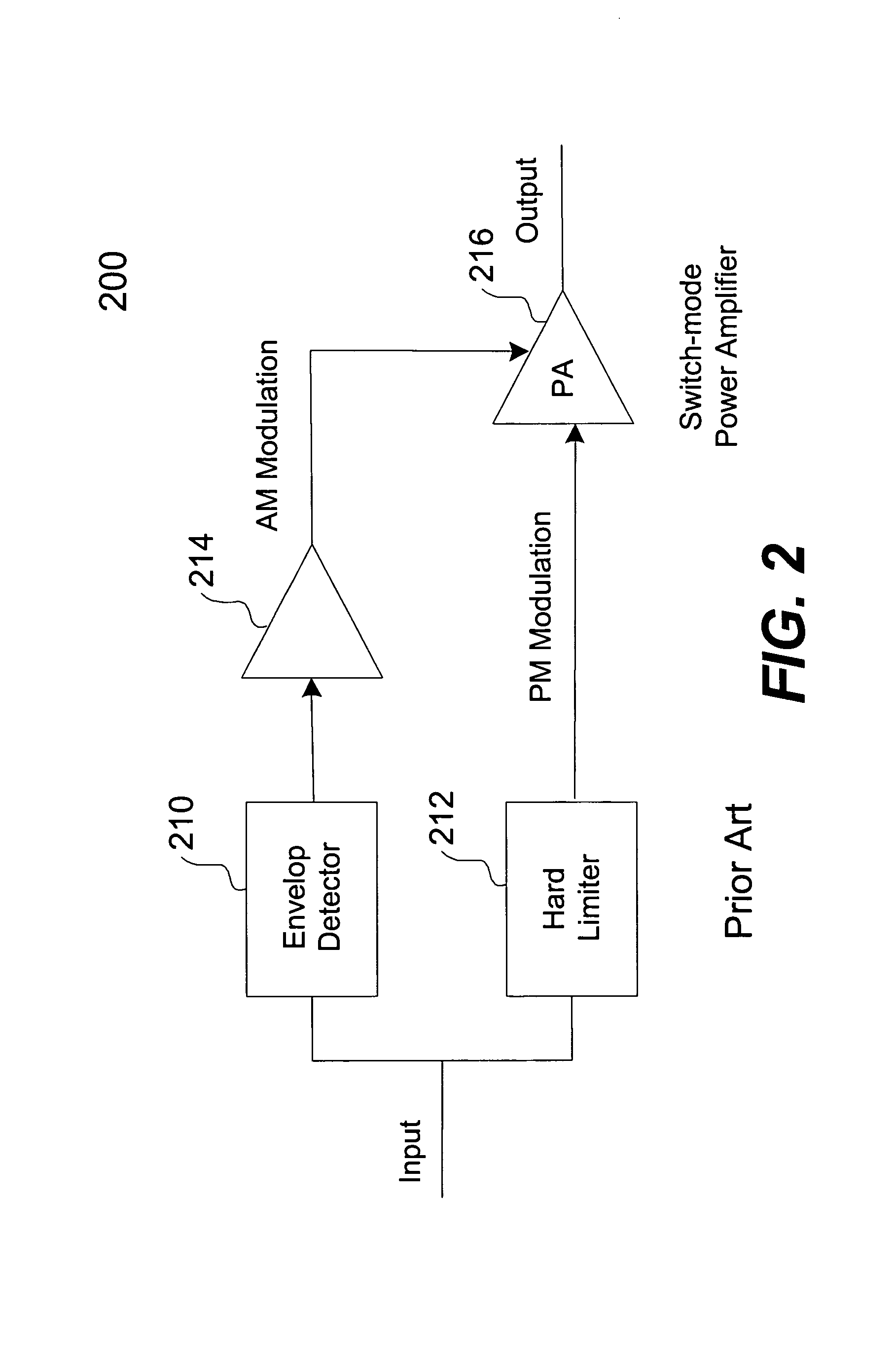
These non-linearities are due to the fact that the amplifier's gain and phase characteristics change with a change in the power supply voltage, and thus the signal dependent power supply voltage is a source of amplitude to amplitude (AM-AM) and amplitude to phase (AM-PM) distortion.
However, this approach is not efficient and suitable for the phase modulation with different modulation standards.

Method used


Image

  • Direct modulation of a power amplifier with adaptive digital predistortion
  • Direct modulation of a power amplifier with adaptive digital predistortion
  • Direct modulation of a power amplifier with adaptive digital predistortion

Examples


Embodiment Construction

[0035]The present invention pertains to a generic RF transmitter architecture using a switching-mode power amplifier to maximize the power efficiency and method therefor. According to one aspect of the present invention, a transmitter design architecture is provided to use amplitude and phase information to directly modulate a switching-mode power amplifier with adaptive digital predistortion. The digital predistortion includes a demodulation feedback path to detect the amplitude and phase signals generated by the power amplifier, and adaptively correct the non-linear effects of the switching-mode power amplifier. The timing mismatch between the amplitude and phase signals is also adaptively compensated by using digital predistortion.

[0036]The detailed description of the present invention is presented largely in terms of functional blocks, procedures, logic blocks, processing, or other symbolic representations that directly or indirectly resemble the operations of a RF transmitter t...


PUM


Abstract

Techniques for direct modulation of a switching-mode power amplifier with adaptive digital predistortion are disclosed. A baseband digital modulated signal is decomposed into an amplitude signal and a phase signal in polar coordinates. The amplitude signal is used to modulate supply voltages of the power amplifier. The phase signal is used to modulate a voltage-controlled oscillator (VCO) of a phase-locked loop (PLL), which generates a phase-modulated radio-frequency (RF) carrier coupled to the input of the power amplifier. The digital predistortion is implemented by using a feedback demodulator, which regenerates the baseband amplitude and phase information from the output of the power amplifier. The VCO drift and other non-linear effects of the power amplifier are compensated. High power efficiency and high linearity for different modulation standards are achieved.

Description

CROSS REFERENCE TO RELATED APPLICATION[0001]This application claims the benefit of U.S. Provisional Application entitled “Direct Power Amplifier Modulation With Adaptive Digital Predistortion”, No. 60 / 404,950, filed on Aug. 21, 2002, the content of which is hereby incorporated by reference for all purpose in its entirety.BACKGROUND OF THE INVENTION[0002]1. Field of the Invention[0003]The present invention relates generally to the field of digital wireless communications. Specifically, the present invention relates to architectures of a digitally controlled radio frequency (RF) transmitter system. More specifically, the present invention relates to transmitter architectures that can operate in different modulation standards and different frequency bands by using substantially same building blocks.[0004]2. Description of the Related Art[0005]The fast growing demand for mobile communication systems has created many modulation (or speed) standards involving various rates and ways device...

Claims


Application Information

Patent Timeline
IPC IPC(8): H04K1/02H04L25/03H04L25/49
CPCH03F1/0211H03F1/0261H03F1/3247H03F1/3282H03F3/24H04L25/03343H04L27/361H03F2200/207H03F2200/438H03F2200/451
Inventor CAO, WEIXUN
Owner CAO WEIXUN
Learn More