
Sine wave lamp controller with active switch commutation and anti-flicker correction

a technology of active switch commutation and anti-flicker correction, which is applied in the direction of electric variable regulation, process and machine control, instruments, etc., can solve the problems of line harmonics, effort represents a complex engineering task, and the economics of changing out the existing light fixtures and ballasts

Inactive Publication Date: 2010-02-23
SINEWAVE ENERGY TECH LLC
View PDF2 Cites 12 Cited by
  • Summary
  • Abstract
  • Description
  • Claims
  • Application Information

AI Technical Summary

Benefits of technology

The solution provides reliable and economical dimming control for HID lamps, minimizing flicker and harmonic distortion, allowing for mass production and implementation in various environments with standard components, while maintaining efficiency and avoiding costly adjustments.

Problems solved by technology

However, in many installation it is not economical to change out the existing light fixtures and ballasts, creating the need for a lighting controller that can reliably and accurately dim entire banks of existing magnetically ballasted HID lamps at the contactor control point.
Given that standard HID lamps and magnetic ballasts were not originally designed to be dimmable, this effort represents a complex engineering task.
Common problems with HID dimmers include flicker, line harmonics, poor power factor, reliability, and arc extinction during the dimming process.
This process affects the power factor of the ballast and contributes a degree of harmonic distortion to the power line.
This system, which interacts with internal elements of the electronic ballast, cannot be built as an element that is external to the ballast because it requires structural changes in the system of common electronic ballasts.
The disadvantage is that the lighting changes suddenly and power cables must be added to the lighting circuit.

Method used


Image

  • Sine wave lamp controller with active switch commutation and anti-flicker correction
  • Sine wave lamp controller with active switch commutation and anti-flicker correction
  • Sine wave lamp controller with active switch commutation and anti-flicker correction

Examples


Embodiment Construction

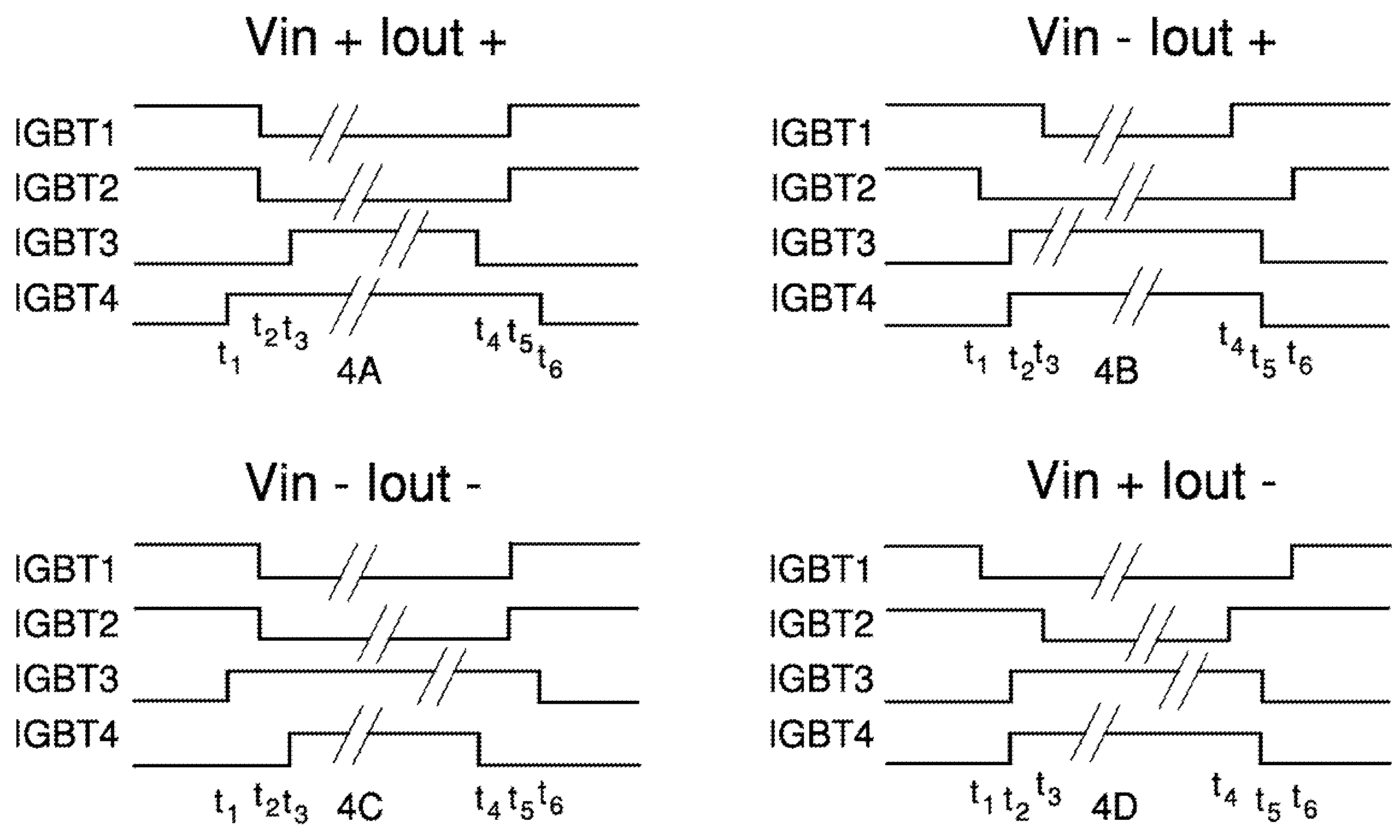
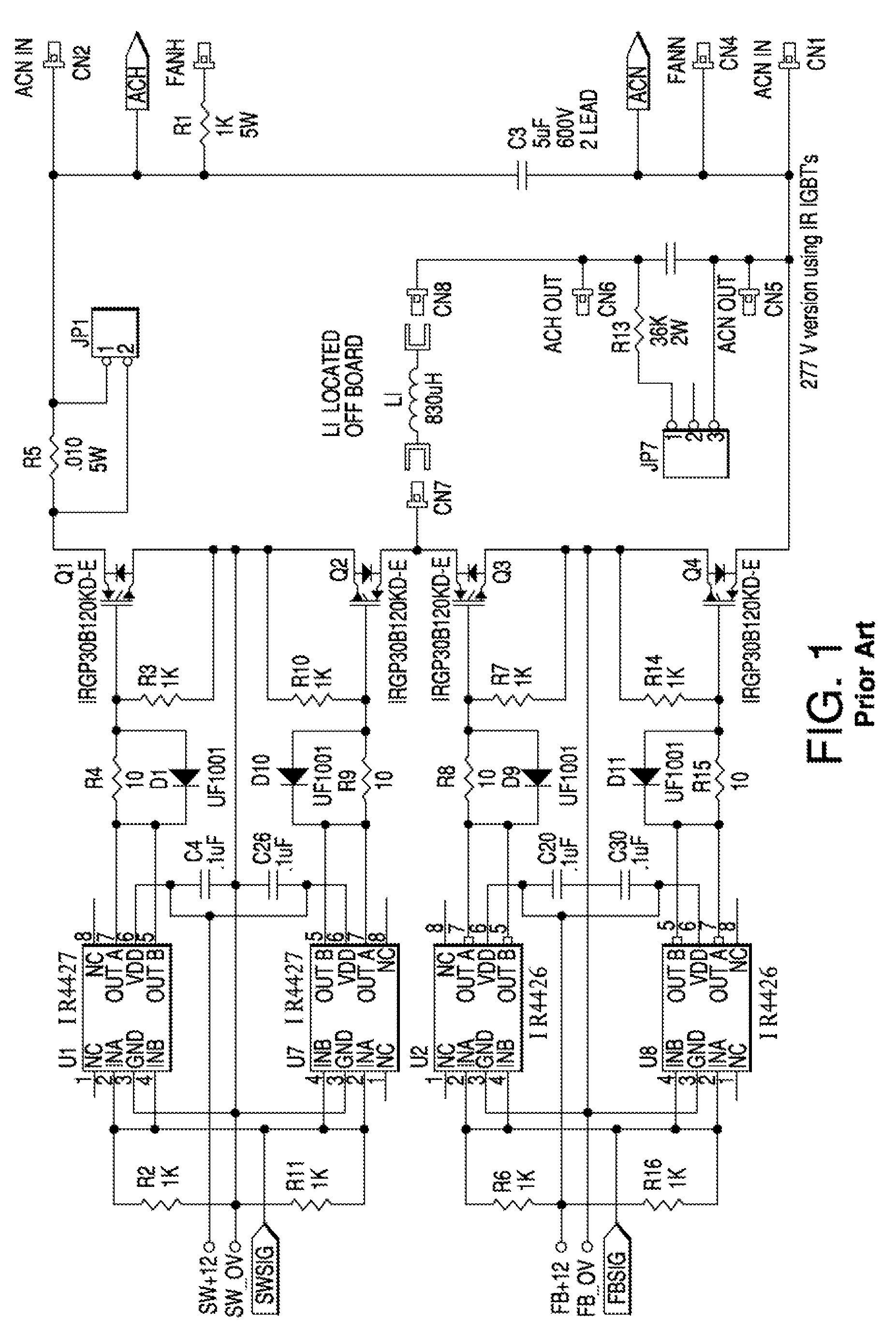
[0023]The present invention modulates the brightness of standard ballasted metal halide lights by adjusting the amplitude of the AC drive voltage delivered to the ballast. Drive frequency is maintained at 60 Hz for all output settings, although the invention can be used with any frequency input. The controller adjusts the output amplitude by varying the duty cycle of a high frequency switching bridge consisting of solid-state IGBT switch elements. The lighting control generates a full four-quadrant, AC waveform to properly drive the lighting ballasts.

[0024]In the current embodiment the AC power input is chopped at a high frequency. The duty cycle of the chopping determines the amount of dimming of the ballast. Dimming can preferably be from full power (100% duty cycle) to no power (0% duty cycle).

[0025]While in the current embodiment the switch elements are IGBTs, other types of power transistors, such as MOSFETS or bipolar transistors may be used including future invented power swi...


PUM


Abstract

A pulse width modulated half bridge dimming controller is provided for dimming a lighting ballast is described. The top half of the bridge is comprised of two switches, the top switch set, and the bottom half of the bridge is comprised of two switches, the bottom switch set. Each switch also has a diode in parallel with it. The drivers for the switches are configured so that each of the switches can be turned on and off independently of all of all the other switches. Preferably, the controller is capable of operating in all four quadrants. In one preferred embodiment the switches are IGBTs. The switches are controlled in a manner so that when one of the switches sets changes states, the second switch set has one switch on and one switch off, so that one of the diodes in the second switch set is disposed to block shoot through and provide a path to allow current to continue flowing in the inductive load.

Description

CROSS-REFERENCE TO RELATED APPLICATIONS[0001]The present application claims the benefit of U.S. Provisional Application No. 60 / 807,774 filed on Jul. 19, 2006, which is incorporated herein by reference.STATEMENT REGARDING FEDERALLY SPONSORED RESEARCH OR DEVELOPMENT[0002]The present invention was not developed with the use of any Federal funds but was developed independently by the inventor.BACKGROUND OF THE INVENTION[0003]High Intensity Discharge (HID) lamps are widely used in airports, parking garages and on public streets to provide wide-area ambient lighting. Although recent electronic ballast designs can deliver better efficiency, improved power factor and longer bulb life than the standard magnetic ballast, most of the HID lamps currently in use employ magnetic ballasts, owing to their low cost, familiar characteristics and their decades-old domination of the HID and fluorescent lighting markets.[0004]Given the ever increasing demands to improve energy efficiency of existing bui...

Claims


Application Information

Patent Timeline
Patent Type & Authority Patents(United States)
IPC IPC(8): H02M7/5387
CPCH05B41/282H05B41/3927Y02B20/183Y02B20/00
Inventor LEYH, GREGORY E.
Owner SINEWAVE ENERGY TECH LLC
Learn More