
I/Q timing mismatch compensation

a timing mismatch and compensation technology, applied in the field of demodulation techniques, can solve problems such as the degree of phase mismatch, the loss of gain between the two channels, and the adverse influence of image rejection performan

Active Publication Date: 2005-11-03
SILICON LAB INC
View PDF5 Cites 22 Cited by
  • Summary
  • Abstract
  • Description
  • Claims
  • Application Information

AI Technical Summary

Benefits of technology

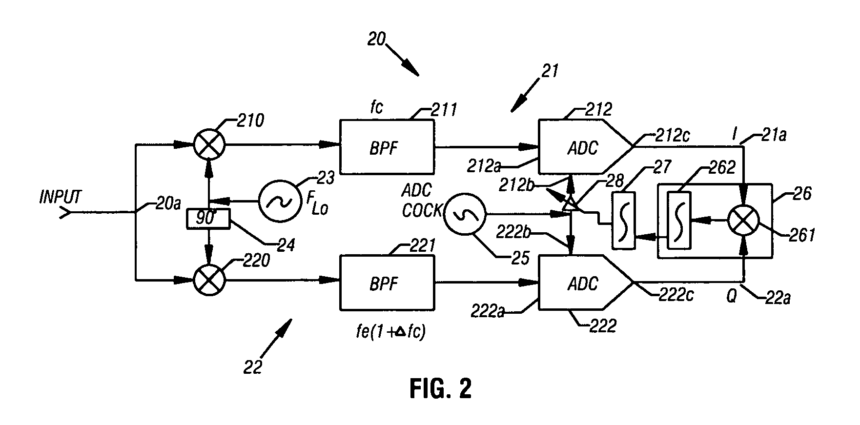
[0011] In a further embodiment, a method for correcting timing mismatch correlation in an I / Q modulator comprises correlating an I-channel signal and a Q-channel signal. A timing signal is derived from the correlation and is applied to either the I-channel or the Q-channel so as to effect correction in the timing mismatch between the channels.
[0012] In another embodiment, a demodulator comprises a first channel to provide a first demodulated output and a second channel to provide a second demodulated output. A correlator is coupled to the first channel and to the second channel to provide a output indicative of a mismatch between the first channel and the second channel. A correction stage is coupled to the correlator to provide a correction signal to a channel so as to effect correction of the mismatch.

Problems solved by technology

In the context of I / Q demodulator receivers, image rejection performance is known to be adversely affected by mismatch that is inevitably introduced between the I-channel and the Q-channel of the demodulator.
First, some degree of phase mismatch may be contributed by the LO signal.
Second, there may exist some mismatch in gain between the two channels.
Gain mismatch may derive, for example, from differences in the conversion gains of the two mixers, and from asymmetry in the performance of gain stages, if any, in the respective channels.
Third, there may exist delay (or timing) mismatches between the channels.
Although it is not uncommon for high-performance image-rejection mixers to incorporate some form of gain and / or phase mismatch compensation, there appears no entirely satisfactory technique to correct timing mismatch, particularly for systems in which the IF is relatively high, say 40 MHz or so.
Accordingly, timing mismatch persists as a concern in the many emerging receiver system designs that are predicated on such IFs.
In receiver systems that incorporate a high IF, timing mismatch is particularly detrimental in that it becomes a source of significant degradation in image rejection.
This is because, as the IF increases, the phase mismatch that results from a given timing mismatch increases accordingly.
Conventional phase-mismatch correction techniques are unavailing as a solution.
However, timing mismatch is related to a nonideal phase / frequency response, specifically, a phase response that does not vary linearly with frequency.
In addition, the use of a digital complex equalizer tends to be cost prohibitive and, nevertheless, only marginally effective.
Accordingly, at present there appears no readily available technique to compensate for timing mismatch in I / Q demodulator systems.

Method used


Image

  • I/Q timing mismatch compensation
  • I/Q timing mismatch compensation
  • I/Q timing mismatch compensation

Examples


Embodiment Construction

[0020] For a thorough understanding of the subject I / Q timing mismatch compensation technique, reference may be had to the following Detailed Description, including the appended Claims, in connection with the above described drawings.

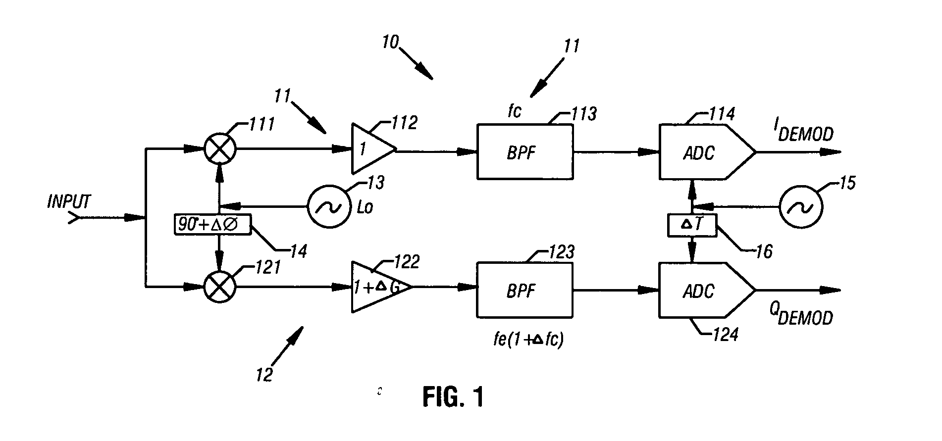
[0021] Referring now to FIG. 1, depicted there is a simplified representation of a conventional I / Q demodulator 10, in which there is graphically represented a number of the potential sources of mismatch that may arise between a representative I-channel 11 and a representative Q-channel 12. As may be seen in FIG. 1, an input signal, in the form of a modulated carrier, is concurrently coupled to the I-channel and to the Q-channel. Specifically, the modulated input signal is coupled to an I-channel mixer 111 and to a Q-channel mixer 121. An output of an LO 13 is coupled directly to I-channel mixer 111 and through a quadrature phase shifter 14 to Q-channel mixer 121. Quadrature phase shifter 14 imparts a nominal 90° phase shift in the output of LO 13.

[00...


PUM


Abstract

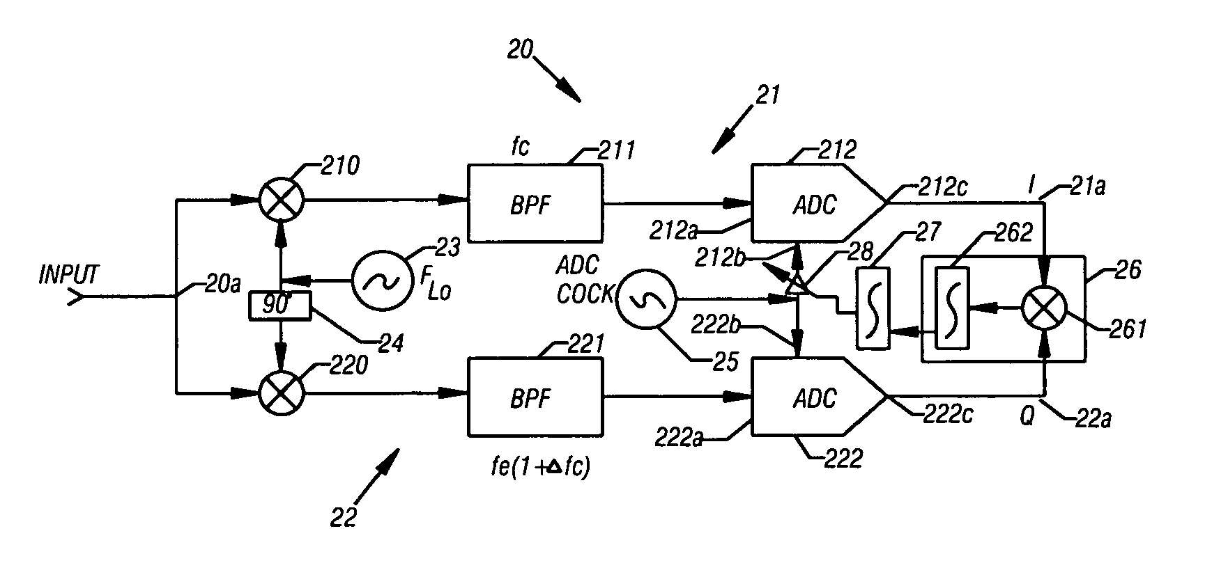
Timing correction is effected for mismatch between channels in an I / Q demodulator. The respective demodulated I-channel and Q-channel are correlated and integrated so generate a timing control signal that is applied to a variable delay element. The variable delay element inserts a variable time delay in an ADC clock signal that is applied to either the I-channel ADC or the Q-channel ADC.

Description

FIELD OF THE INVENTION [0001] The invention relates generally to demodulation techniques and, more particularly, to a technique to correct timing mismatch between the channels of an I / Q demodulator. BACKGROUND [0002] I / Q (In-phase / Quadrature) modulators and demodulators are widely used in digital communications systems and are abundantly discussed in the technical literature. See, for example, Behzad Razavi, RF Microelectronics, Prentice Hall (1998) and John G. Proakis, Digital Communications, McGraw-Hill (1995). Examples of system applications that incorporate and standardize I / Q modulation and demodulation include the GSM (Global System for Mobile Communications), IS-136 (TDMA), IS-95 (CDMA), and IEEE 802.11 (wireless LAN). I / Q modulation and demodulation have also been proposed for use in short-range radio systems such as Bluetooth wireless communication systems. [0003] Typically, in a receiver system that incorporates I / Q demodulation, the modulated carrier is simultaneously app...

Claims


Application Information

Patent Timeline
Patent Type & Authority Applications(United States)
IPC IPC(8): H04L27/22H04L27/36
CPCH04L27/364
Inventor KHOINI-POORFARD, RAMIN
Owner SILICON LAB INC
Learn More