Ankle-foot orthosis
a technology for ankles and feet, applied in the field of ankle-foot orthosis, can solve the problems of limited ankle-foot orthoses, unsatisfactory orthoses, users with reduced mobility, and decreased quality of life, and achieve the effects of increasing or narrowing the gap between the two, increasing and reducing the stiffness of the orthosis
- Summary
- Abstract
- Description
- Claims
- Application Information
AI Technical Summary
Benefits of technology
Problems solved by technology
Method used
Image
Examples
first embodiment
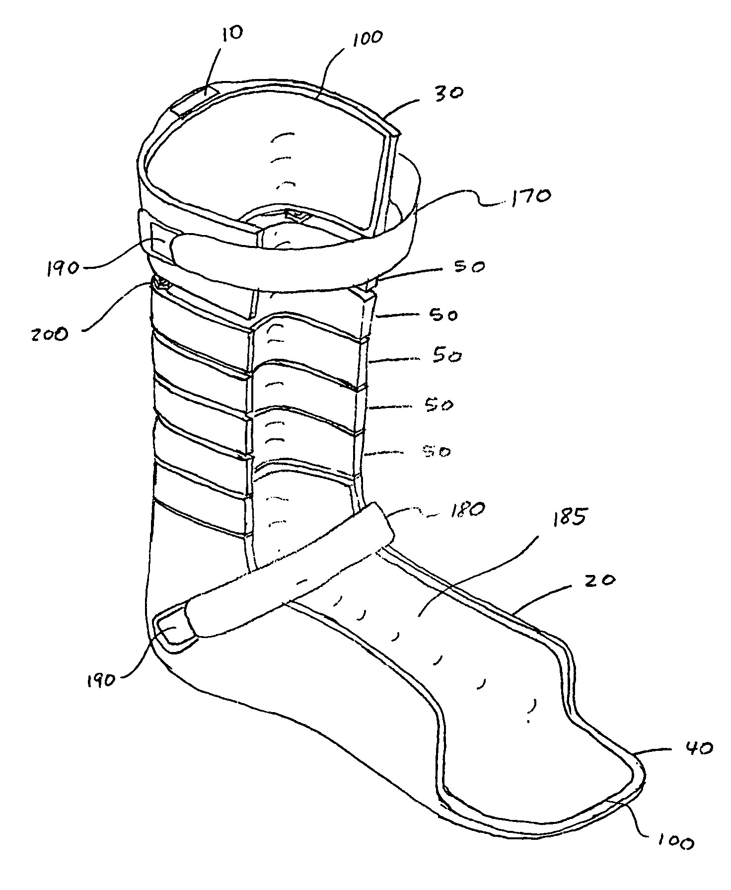
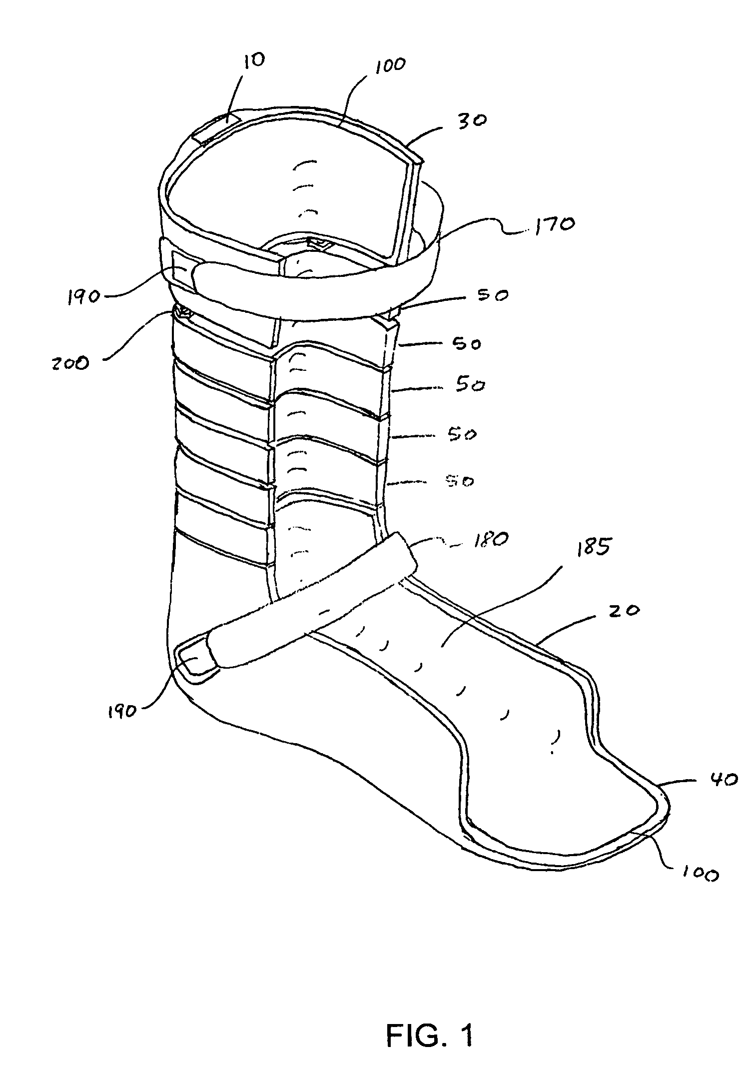
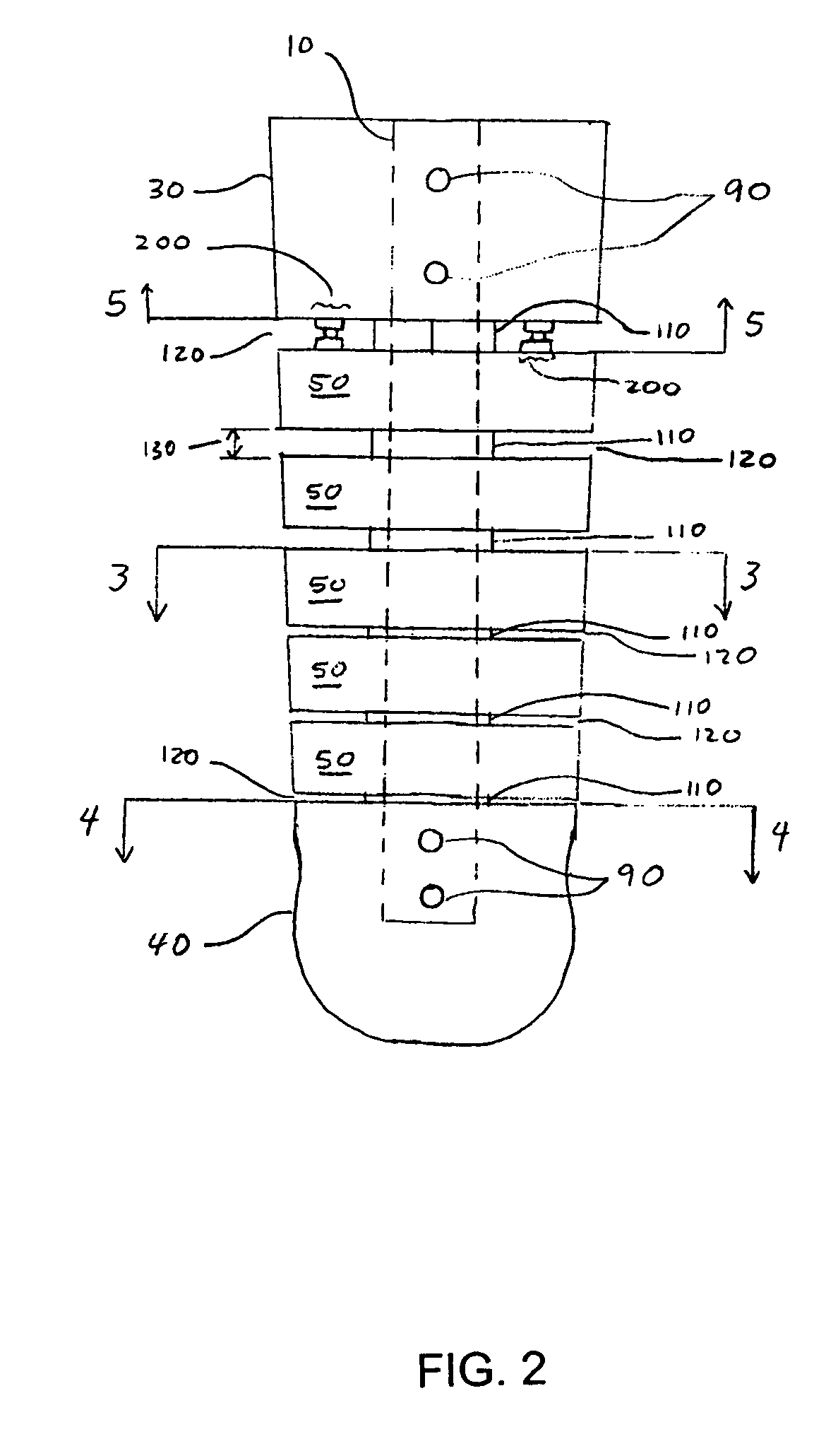
[0056]FIGS. 1 and 2 illustrate an orthosis according to the present invention. The orthosis includes a strut 10 having a foot shell 20 attached to a lower end and a calf shell 30 attached to an upper end. Optionally, the foot shell 20 may include a toe extension 40 for supporting a user's toes, if such support is needed by the user. A plurality of segments 50 extends from the calf shell 30 to the foot shell 20 along a vertical length of the strut 10. In a preferred embodiment, the foot shell 20, calf shell 30, and segments 50 have U-shaped cross-sections. Further, the orthosis includes an adjustment mechanism 200 for adjusting the stiffness of the orthosis, which is described in more detail below.
[0057]Referring to FIG. 3, the segment 50 includes a passageway 60 extending vertically through a back portion thereof, a pair of front edges 160, and a back edge 300. The passageway 60 is configured to accommodate a portion of the strut 10 passing therethrough. As shown in FIG. 4, the foot...
second embodiment
[0074]FIGS. 10 and 11 illustrate the adjustment mechanism 200′, which includes a twist draw mechanism 230. The mechanism 230 is essentially a twist draw latch, sometimes referred to as a butterfly latch. In one embodiment of the mechanism 230, a rotatable member 240 causes a pin 250 attached at a radius of the rotatable member 240 to slide within a slots 260 and 270 provided in a frame member 280 and a slide 290, respectively. The slot 260 restricts the amount of rotation that rotatable member 240 may rotate. The slide 290 is constrained horizontally but not vertically. Therefore, as the pin 250 follows a circular motion of the rotatable member 240 within slot 260, the pin 250 freely moves horizontally within the slot 270, forcing the slide 290 to move vertically within the frame member 280. As a result, the circular motion is translated into a purely vertical motion. Consequently, when the mechanism 230 is attached to the posterior of the calf shell 30, for example, a lower edge of...
third embodiment
[0078]the present invention is illustrated in FIG. 13. In such an embodiment, a hinge 310 is provided between a foot shell 320 and a lowermost segment 330, wherein one end of the hinge 310 is inserted into an opening 340 extending vertically through a posterior portion of a foot shell 320 and a second end is inserted into a passageway 350 extending vertically through a lower portion of the lowermost segment 330. A lower end of a strut 360 occupies an upper portion of the passageway 350 in the lowermost segment 330. Alternately, the hinge 310 can be located between any two adjacent segments 330. The hinge 310 can also be disposed between a calf shell 370 and the uppermost segment 330. Further, it is within the scope of the present invention that more than one hinge 310 be used.
[0079]The hinge 310 eliminates essentially all stiffness of the orthosis in both dorsiflexion and plantar flexion at a location where the hinge 310 is disposed, until, in dorsiflexion, front edges 400 of the se...
PUM
 Abstract
Description
Claims
Application Information
 - R&D
- Intellectual Property
- Life Sciences
- Materials
- Tech Scout
- Unparalleled Data Quality
- Higher Quality Content
- 60% Fewer Hallucinations
Browse by: Latest US Patents, China's latest patents, Technical Efficacy Thesaurus, Application Domain, Technology Topic, Popular Technical Reports.
© 2025 PatSnap. All rights reserved.Legal|Privacy policy|Modern Slavery Act Transparency Statement|Sitemap|About US| Contact US: help@patsnap.com


