
Techniques for building-scale electrostatic tomography

a technology of electrostatic tomography and building scale, applied in the field of electrostatic tomography, can solve the problems of ineffective infrared, acoustic and radiation systems, ineffective infrared sensors, and few sensor technologies that effectively image the interior of building structures or densely foliated expanses,

Active Publication Date: 2008-02-12
MITRE SPORTS INT LTD
View PDF77 Cites 34 Cited by
  • Summary
  • Abstract
  • Description
  • Claims
  • Application Information

AI Technical Summary

Benefits of technology

The patent describes a system for detecting target objects inside a search region using electrostatic imaging. The system includes multiple electrodes placed around the search region, with some electrodes being moveable. The system uses emitter circuits to produce an electric field with a wavelength longer than one hundred meters. The system measures the properties of the electric field produced by the emitter circuits and the receiver circuits. The processor analyzes the data to determine the presence and orientation of target objects. The system can also adapt to changing tactical conditions and can be used in search and rescue situations.

Problems solved by technology

Unfortunately, very few sensor technologies effectively image the interior of building structures or densely foliated expanses.
Infrared, acoustic and radiation systems are often ineffective.
Thus, infrared sensors are ineffective where the humans are in interior chambers, or are deeply buried, or in circumstances where humans, who are in contact with the inside surfaces of exterior walls, are also moving.
Acoustic sensors are ineffective for similar reasons.
Thus, acoustic sensors are often ineffective, where the humans are in interior chambers, or are deeply buried.
Radiation systems are ineffective for several reasons.
For example, high frequency electromagnetic radiation used in RADAR (radio detection and ranging) systems do not effectively penetrate buildings.
Very high frequency, high energy radiation, such as X-ray systems, gamma ray systems, and neutron systems either penetrate the humans of interest nearly as effectively as the walls, giving very low contrast signals that are difficult or expensive to process, or produce so much ionizing activity so as to be harmful to the humans being detected.
A system that injures the humans to be detected renders the system useless for search and rescue, for discriminating friendly forces from hostile forces or for situations, such as in an urban surrounding, where non-combatants may be exposed to excessive levels of ionizing radiation.
These single pole measurement devices do not estimate location or electrical properties of hidden materials, but merely detect changes in those electrical properties.
Their measurement data lacks the spatial and geometric information required for a tomographic inversion to reconstruct an image based on the intruder and surrounding space.
There is no practically feasible way a system like this could be used to distinguish proximate intruders from other conducting objects.
These systems do not detect, locate or characterize target objects, including biological organisms, cached in a large structure, such as a building.
However, this system relies on sensors that are embedded in the same conducting medium as the target, i.e., seawater, and that have fixed, unchanging geometries within the space being monitored.
None of these systems account for the complexities in electrostatic field measurements caused by the presence of buildings and building materials with unknown building components.
For example, no current EFT systems account for the impact on electrostatic fields of walls and metal conduits for electrical, water, and air ducts or the varying effects of wood, concrete and other construction materials that have unknown or only partially known distributions in a region of interest.
Such systems would not work for detecting sleeping or stationary humans, for example.
These EFT systems also involve fixed and static geometries for sensors that make it difficult to adapt them to buildings of arbitrary shape and size and rapidly changing tactical situations.
Inversions using such pre-computed quantities cannot be performed for electrode spacing that is changing on tactical scales.
No systems exploit the properties of electrostatic fields to detect, locate and characterize one or more dielectric or conducting target objects, including biological entities, inside of at least partially unknown and variable building-sized regions.

Method used


Image

  • Techniques for building-scale electrostatic tomography
  • Techniques for building-scale electrostatic tomography
  • Techniques for building-scale electrostatic tomography

Examples


embodiment 380

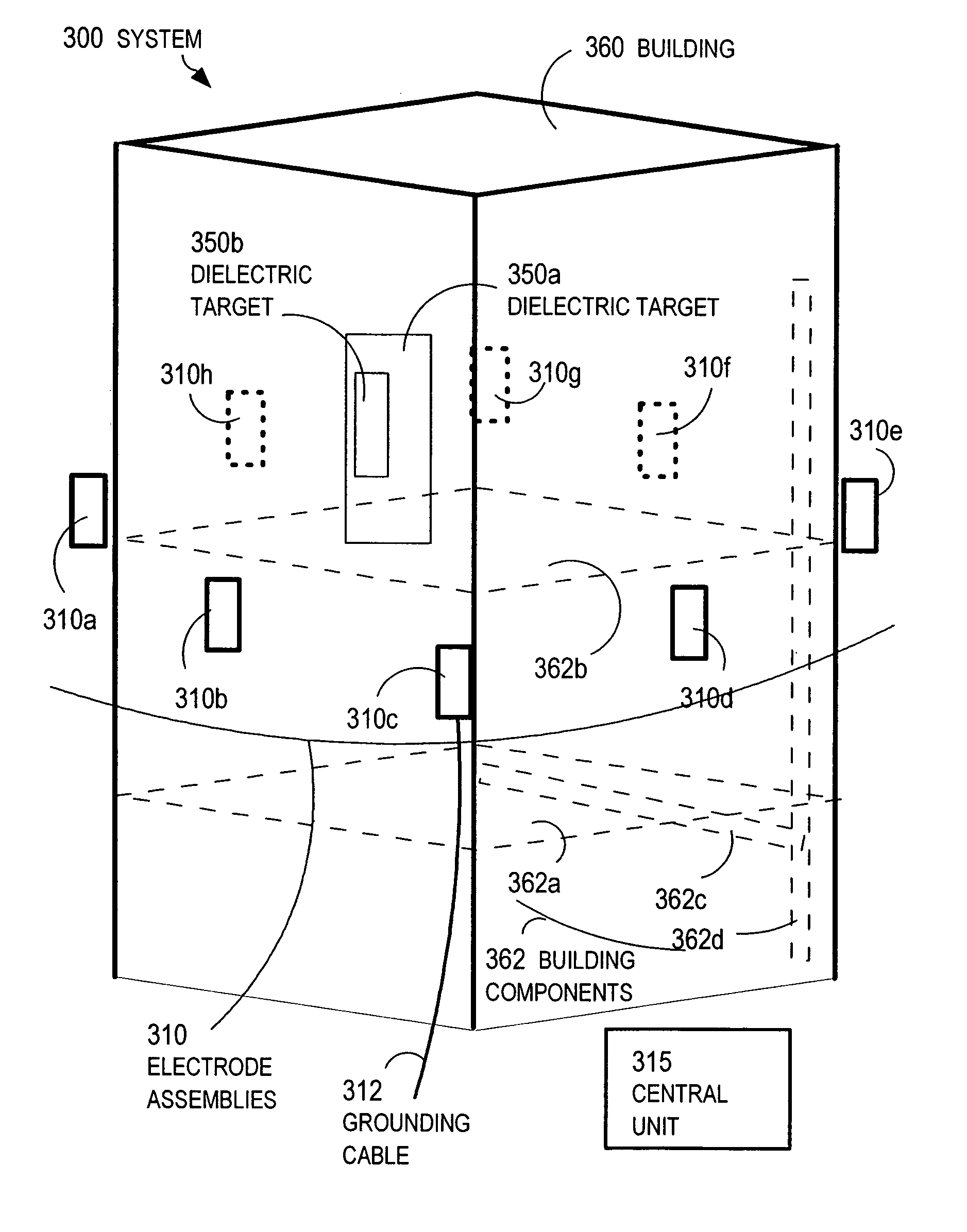
[0118]FIG. 3C is a block diagram that illustrates an electrode assembly, according to an embodiment 380. The electrode assembly 380 includes a power supply 381, an electrode 386, an emitter circuit 387 and a receiver circuit 388. In addition, the electrode assembly 380 includes a communication system 382, a positioning system 383, a processor 385, and a movement mechanism 384.

[0119]The power supply 381 provides power for the emitter circuit 367, receiver circuit 388, processor 385, communication system 382 and positioning system 383. Any power supply known in the art may be used, including any electrical power supply. Although shown as a separate component in FIG. 3C, in other embodiments the power supply 381 is part of one or more of the other components. In the illustrated embodiment, the movement mechanism 384 includes a separate power supply for a different kind of power. In other embodiments, the movement mechanism is powered by power supply 381.

[0120]In the illustrate embodime...

embodiment 390

[0131]FIG. 3D is a block diagram that illustrates a central unit, according to an embodiment 390. The central unit 390 includes a power supply 391, a communication system 392, a positioning system 393, a processor 395, and a display 396.

[0132]The power supply 391 provides power for the other components. Any power supply known in the art may be used, including any electrical power supply. Although shown as a separate component in FIG. 3C, in other embodiments the power supply 391 is part of one or more of the other components.

[0133]The communication system 392 is a component that receives information from the electrode assemblies 310, such as electrode assembly 380. Any method known in the art may be used for the communication system, including tethered and wireless communications systems using radio, optical or other transmission signals. For example, the communication system 392 receives data indicating the electric potential measured by the receiver circuit 388 on electrode assemb...


PUM

PropertyMeasurementUnit
distancesaaaaaaaaaa
dielectric constantaaaaaaaaaa
dielectric constantsaaaaaaaaaa

Abstract

Techniques for imaging a search region to detect a dielectric target include placing multiple electrodes outside the search region. At least two electrodes are activated independently of each other. Emitter circuits are connected to corresponding emitter electrodes. Each emitter circuit is configured for using its emitter electrode to produce an electric field with wavelength longer than about one hundred meters. Receiver circuits are connected to corresponding receiver electrodes. Each receiver circuit is configured for using its receiver electrode to measure a property of an electric field produced, at least in part, by an emitter electrode. A processor determines a property of a dielectric target inside the search region based on measurements from the receiver circuits using a subset of the emitter circuits. Among other uses, these techniques allow humans to be detected inside building-size regions, even when hidden by visually opaque blocking material of small dielectric constant.

Description

CROSS-REFERENCE TO RELATED APPLICATIONS[0001]This application claims benefit under 35 U.S.C. §119(e) to Provisional Patent Application No. 60 / 533,077, filed Dec. 30, 2003, which is incorporated herein by reference in its entirety.STATEMENT REGARDING FEDERALLY-SPONSORED RESEARCH AND DEVELOPMENT[0002]Statement under MPEP 310. The U.S. government has a paid-up license in this invention and the right in limited circumstances to require the patent owner to license others on reasonable terms as provided for by the terms of contract No. DAAB07-03-C-N206, awarded by the Defense Advanced Research Projects Agency, the central research and development organization for the Department of Defense.STATEMENT OF GOVERNMENTAL INTEREST[0003]This invention was made in part with Government support under Contract No. DAAB07-03-C-N206 awarded by the Defense Advanced Research Projects Agency (DARPA) Advanced Technology Office (ATO). The Government has certain rights in the invention.BACKGROUND OF THE INVEN...

Claims


Application Information

Patent Timeline
Patent Type & Authority Patents(United States)
IPC IPC(8): G01N27/60G01N23/00G01R29/14G21K7/00
CPCA61B5/0536G01N27/60G01R29/14
Inventor DONNANGELO, NICHOLAS C.
Owner MITRE SPORTS INT LTD
Learn More