Check valve for a trocar system

a check valve and trocar technology, applied in the field of trocar system check valves, can solve the problems of unfavorable manipulation of the flap valve and unfavorable handling of the slide rod, and achieve the effects of reducing the axial dimensions of the flap valve, constant application of force, and compact design

Inactive Publication Date: 2008-01-29
PAJUNK GMBH & CO KG BESITZVERWALTUNG
View PDF14 Cites 5 Cited by
  • Summary
  • Abstract
  • Description
  • Claims
  • Application Information

AI Technical Summary

Benefits of technology

[0011]In the inventive flap valve, the slide rod operating the flap is introduced radially slidable into the housing. The flap valve can thus be opened simply by pushing a radially positioned push button. Therefore, it becomes possible to handle the trocar system and operate the flap valve with one hand in an ergonomically favorable manner. The housing of the flap valve and consequently the trocar system can be held, for example, between the index and middle fingers, whereas the radial operation of the flap valve can be by the thumb. The flap is constructed in the manner of a two-armed lever. The slide rod engages an actuation area that is located on one arm of the flap. The other arm, relative to the pivoting axis of the flap, includes the valve part. Preferably, the operating area is developed immediately in the area of the pivoting axis. Therefore, the operating of the flap doesn't require any additional radial space and the outside diameter of the body can stay at a minimum. In addition, a pivoting of the flap by 90° between the “closed” and “open” positions is possible through a smaller radial stroke—another advantage of the compact design of the flap valve. Especially, the radial slide rod allows a significant reduction of the axial dimensions of the flap valve.
[0012]In a preferred embodiment, the actuation area of the flap is in the form of a curved surface having such a shape that the area that slide rod engages has, in any pivoted position of the flap, as sufficiently large angle to the slide rod axis to initiate a turning moment in the pivoting direction of the flap. Through the pivoting movement of the flap, the actuation area practically slides underneath the inward facing end of the slide rod. Thus, there is a constant application of force and a constant torque over the total linear range of the slide rod and therefore the total pivoting range of the flap. This is of substantial advantage for an ergonomic operation of the flap valve.

Problems solved by technology

The manipulation of the flap valve is unfavorable, because the surgeon has to support the trocar system with one hand and use the other hand for pivoting the valve.
Because of spatial reasons the slide rod must be attached very close to the middle axis of the body, so the handling of the slide rod is ergonomically unfavorable.

Method used


Image

  • Check valve for a trocar system
  • Check valve for a trocar system
  • Check valve for a trocar system

Examples


Embodiment Construction

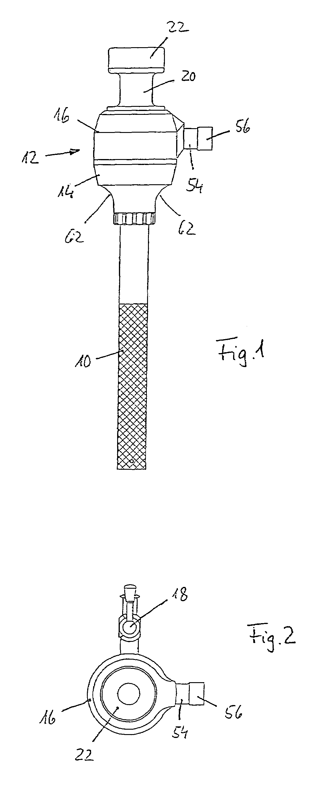
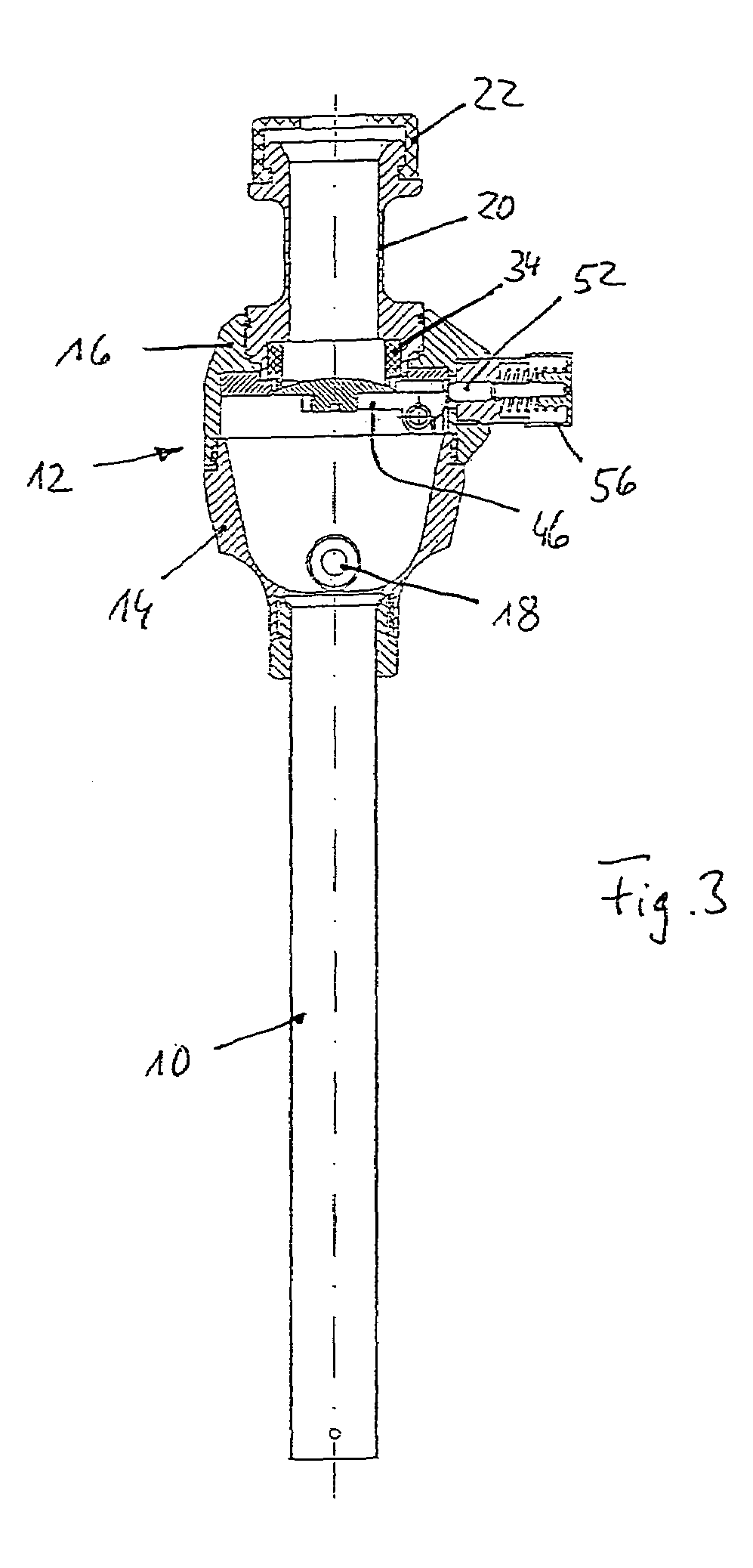
[0022]The trocar system shown in FIGS. 1 through 3 includes a guide tube 10, containing an inserted trocar, not visible in the drawing, serving as instrument channel and access channel for minimally invasive surgery, for example, when inserted through the visceral cavity.

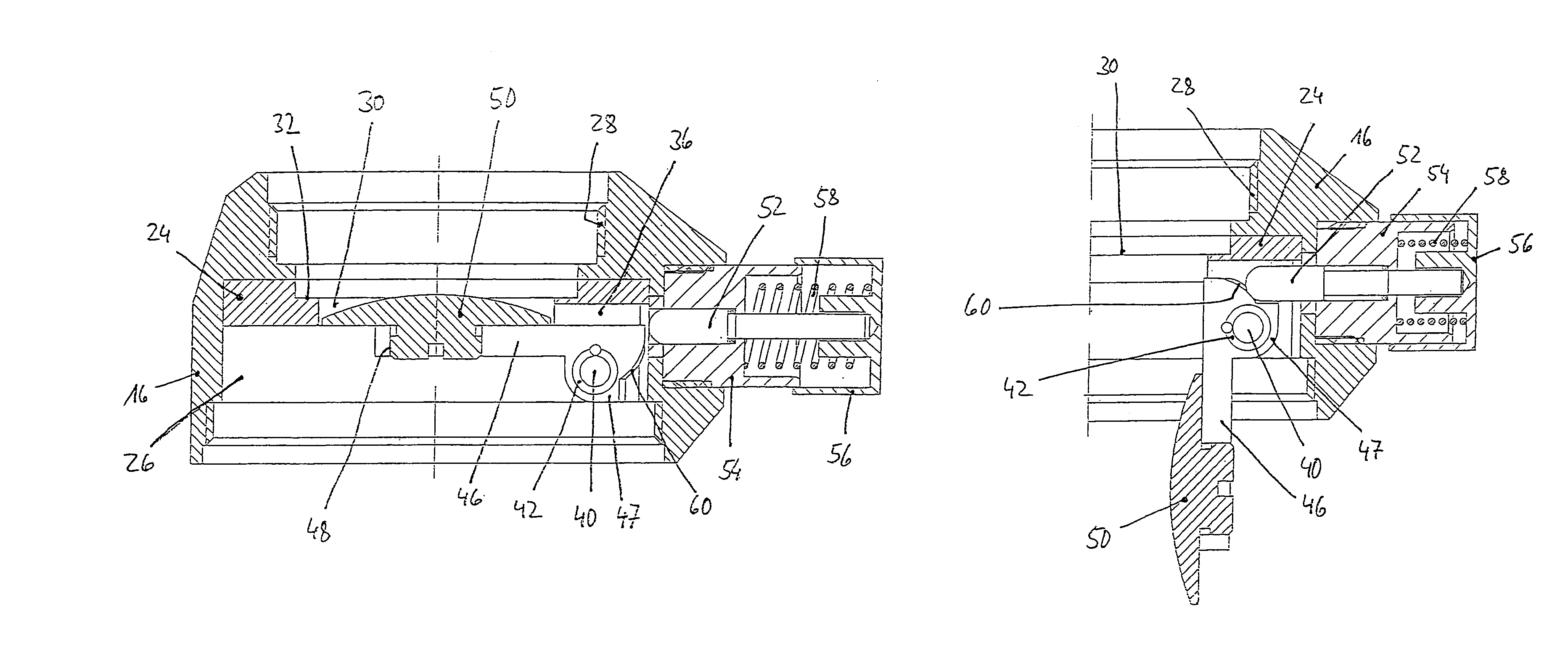
[0023]On the proximal end of the guide tube 10 a housing 12 is seated axially flush, comprising a base part 14 and a flap body 16. An insufflation stop-cock or valve 18 leads into the base part of the housing, through which gas can be injected into the visceral cavity. The flap body contains the flap valve, which is described in detail below. A hollow insertion shaft 20 is proximally screwed in sealed manner into the flap body 16, which is aligned axially with the insertion tube 10 and also exhibits the same inner diameter. On the proximal end of the insertion shaft 20, a soft elastic rubber covering 22 is attached, which exhibits a central opening and a diameter slightly smaller than the inner diameter of the inser...


PUM


Abstract

A flap valve for a trocar system including a valve housing (12) that is proximally attachable to a guide tube (10), a lead-through opening (30) formed in the valve housing (12), and a pivotally mounted flap valve (46). The flap valve (46) is manually pivotable from a “closed” position to an “open” position via a slide rod. The slide rod (52) is mebedded in the body (12), is radially slidable and contacts with its inner end an actuation area of the flap valve (46).

Description

BACKGROUND OF THE INVENTION[0001]1. Field of the Invention[0002]The invention concerns a flap valve for a trocar system according to the preamble of a patent 1.[0003]2. Description of the Related Art[0004]Trocar systems are being used in minimally invasive surgery to enable entrance to a body cavity, for example, into the visceral cavity. For this procedure, a guide tube (trocar cannula) with a trocar (obturator) inserted therein is passed through the abdominal wall. Subsequently, the trocar is removed and the guide tube remains as an access canal to the visceral cavity. In order to perform surgical procedures in the visceral cavity, it typically is insufflated. To avoid gas leakage from the visceral cavity, a valve is placed at the extracorporeal remaining proximal end of the guide tube, which closes automatically if no instrument is inserted.[0005]To enable the insertion of a delicate instrument and avoid the entanglement of instruments during extraction, flap valves are used that...

Claims


Application Information

Patent Timeline
IPC IPC(8): A61M5/00A61B17/34
CPCA61B17/3498
Inventor PAJUNK, HEINRICHPAJUNK, HORST
Owner PAJUNK GMBH & CO KG BESITZVERWALTUNG
Why Eureka
Try Eureka