
Modular adsorbent filters

a filter and module technology, applied in the field of modules, can solve the problems of static friction or “stiction” of the contamination-related failure mechanism of the computer disk drive, the filter is incapable of fully addressing the growing need for even smaller and more compact filters, and may cause damage to external contaminates as well as out-gassing from internal components

Active Publication Date: 2008-01-15
Z KURODA (THAILAND) CO LTD
View PDF29 Cites 20 Cited by
  • Summary
  • Abstract
  • Description
  • Claims
  • Application Information

AI Technical Summary

Benefits of technology

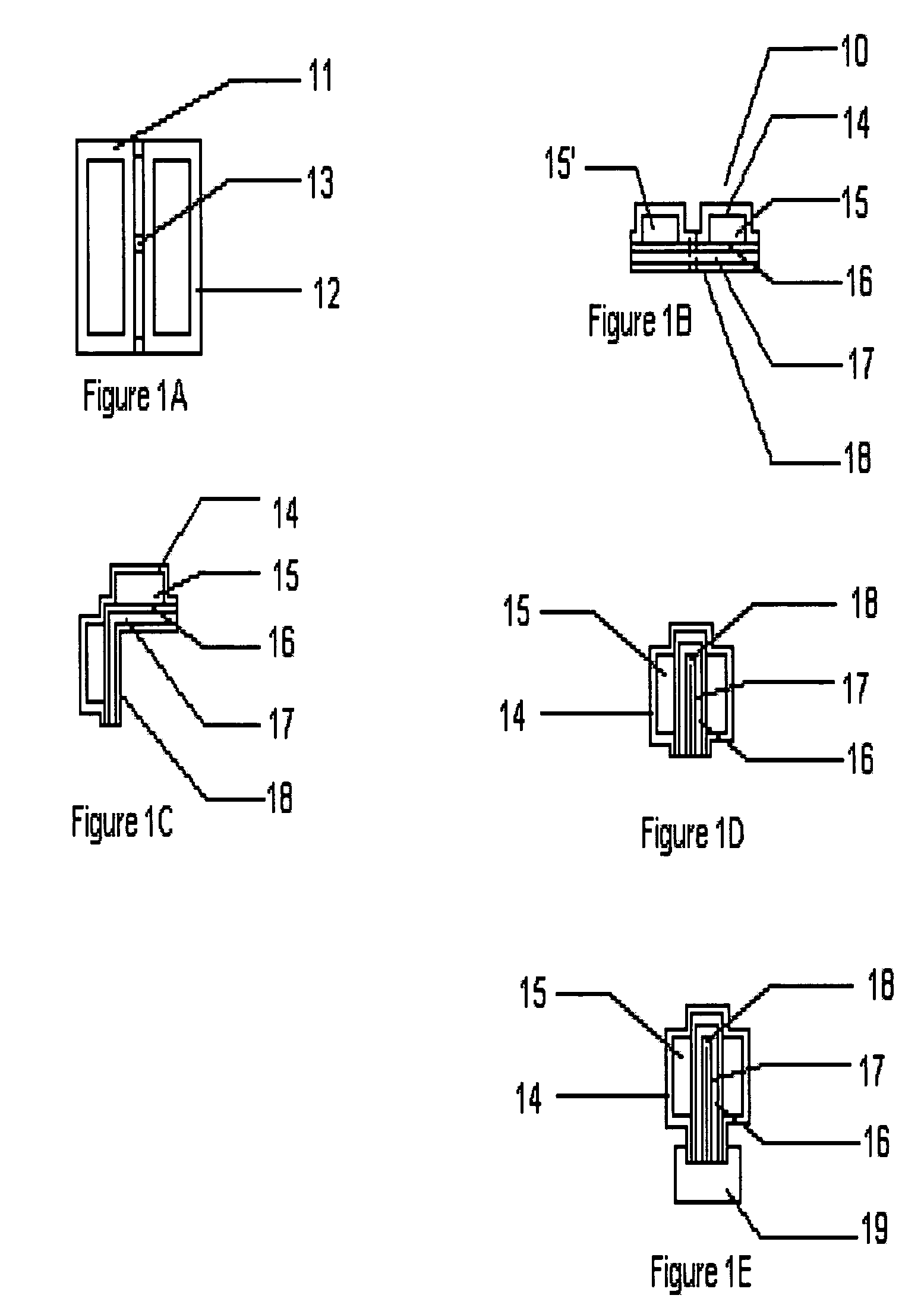
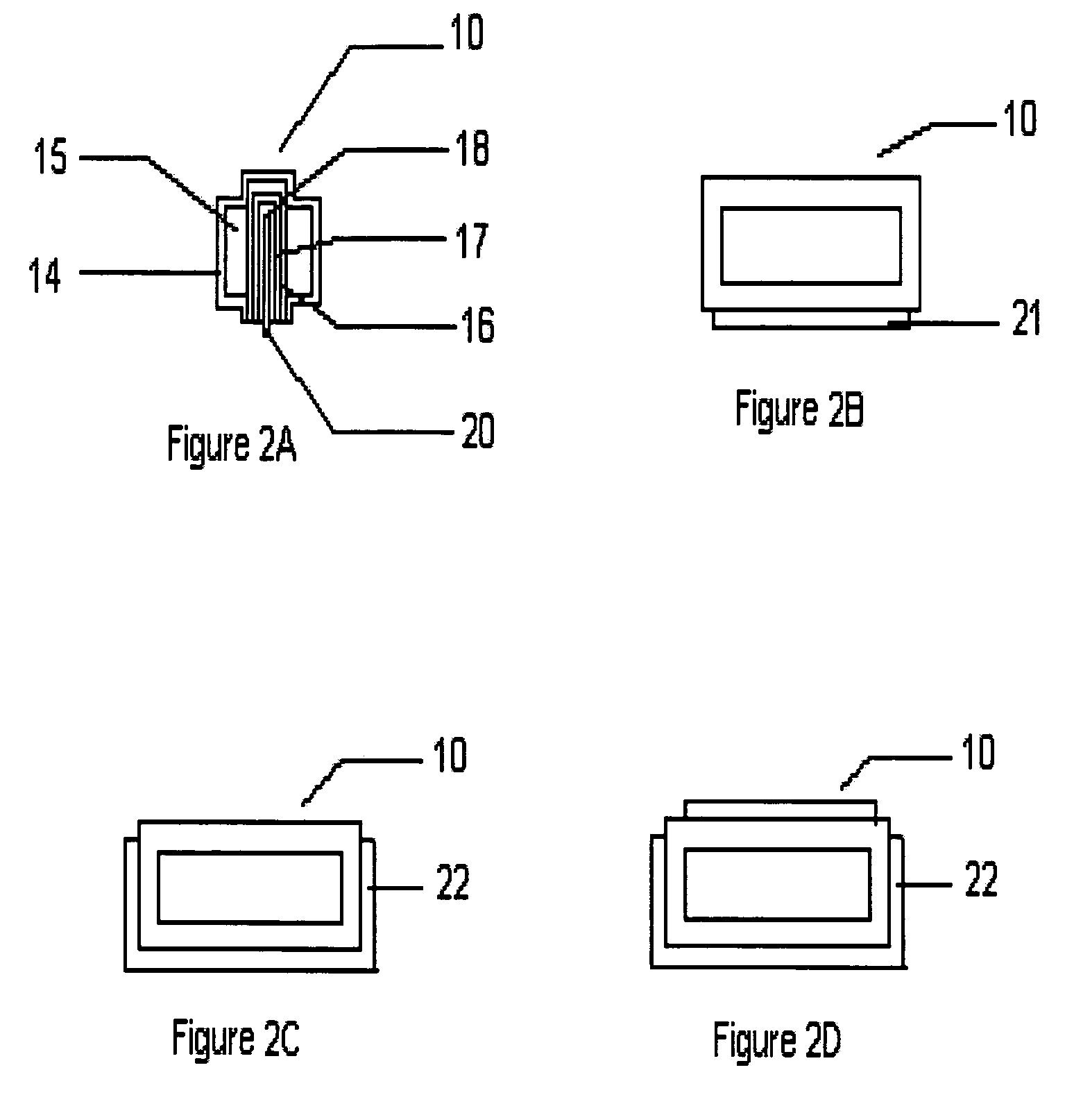
"The present invention provides an adsorbent assembly for removing contaminants from an enclosure. The assembly includes two adsorbent assemblies that are foldable connected. The first adsorbent assembly has a first substrate and a first porous polymeric layer covering at least a portion of the first adsorbent. The second adsorbent assembly has a second substrate and a second porous polymeric layer covering at least a portion of the second adsorbent. The two adsorbent assemblies are folded along a fold line and can be folded up to fit into a corner of an enclosure. The invention also provides an adsorbent media comprising an adsorbent and a polymer layer. The technical effects of the invention include improved adsorption performance and flexibility in application."

Problems solved by technology

Contamination in such enclosures originates from both inside and outside the enclosures.
For example, in computer hard drives, damage may result from external contaminates as well as out-gassing from internal components.
One serious contamination-related failure mechanism in computer disk drives is static friction or “stiction.” Stiction is the adhesion of a drive head to a disk while the disk is stopped.
Contaminants on the disk change the surface energy and the adhesive forces between the disk and the head, which causes stiction.
Also, vapors that condense in the gap between the head and disk can cause stiction.
In its present form, this filter is incapable of fully addressing growing needs for even smaller and more compact sorbent filters containing a higher sorbent density.
Sorbent filter manufacturers have encountered several obstacles in producing very small tube sorbent filters.
As tube size (diameter) decreases, filling the tube with sorbent powder becomes more difficult.
This problem is compounded by the common use of larger granular sorbent powders commonly used to avoid ‘dusting’ contamination.
It is more difficult to fill the small tube filters without having the powder settle on the external tube surfaces and the seal areas.
The powder on the outside of the tube can contaminate the devices near the tube and powder in the seal area can prevent the outer tube from sealing, which may also cause dusting problems through leakage.
However, the use of loose particles in existing filled tube filters, if broken, could spill the loosely packed adsorbent material into the enclosure, damaging the integral components.
Another problem with tubular sorbants is that they require custom automation in production.
The rapid development and obsolescence of materials and parts in the disk drive filtration industry makes such custom automation undesirable.
Although this sorbent assembly provides a low profile compact sorbent assembly, concern has been expressed that the unsealed sides of this device may not provide adequate protection from shedding of sorbent material particles in some applications.
However, known rotary die cutting equipment imposes significant limitations on adsorbent assembly and adsorbent breather filter design.
This substantially limits total adsorbent capacity for an adsorbent assembly.
Thicker adsorbents have also required complex molding of the porous membrane cover to cover and seal the adsorbent within the filter.
There are also some other limitations in part designs (such as exposed adhesives), part layers, and the ability to automatically pick and place parts from some rotary processed layouts that can limit the use of these parts.
Also there can be limitations on the number of parts per foot that can be made from raw materials that increase per part costs.

Method used


Image

  • Modular adsorbent filters
  • Modular adsorbent filters
  • Modular adsorbent filters

Examples


example 1

[0131]An adsorbent assembly was made having the following features. A polyester film or sheet having a thickness of 0.003 inches was coated with an adhesive on two sides. The adhesive was 0.0015 inch thick high temperature acrylic pressure sensitive adhesive. This double sided adhesive construction is available from Adhesives Research company in Glenn Rock Pa.

[0132]A 70 wt % activated carbon and 30 wt % PTFE adsorbent core was made by in accordance to U.S. Pat. No. 4,985,296:

[0133]The polymeric filter membrane was provided comprising expanded porous PTFE membrane having a 0.2 micron rating as made and supplied by W. L. Gore and Associates, Inc. Newark, Del.

[0134]Two adsorbent pieces were cut and placed on the adhesive coated polyester sheet equidistant from the location of the intended fold line. The porous polymeric membrane was pressed over the adsorbents and adhered to the adhesive on the polyester film around the perimeter of each adsorbent. A perforation was made along the fold...


PUM

PropertyMeasurementUnit
thicknessaaaaaaaaaa
thicknessaaaaaaaaaa
thicknessaaaaaaaaaa

Abstract

A compact sorbent filter for selectively sorbing contaminants and method of removing contamination from an enclosure with a filter is disclosed. Filters of the present invention comprise two or more modular adsorbent units that can be foldably connected and possibly symmetric about one or more axis.In another aspect, the invention provides a laminar support, having at least one edge, a first side and a second side opposite the first side, wherein the article is folded along the fold line about the at least one edge of the laminar support such that the first adsorbent assembly is adjacent to the first side of the laminar support and the second adsorbent assembly is adjacent to the second side of the laminar support. In this aspect, the laminar support may be exposed or covered by the adjacent adsorbent assemblies.

Description

FIELD OF THE INVENTION[0001]This invention relates to devices for filtering or removing contaminants from a confined environment, such as gaseous contaminants in electronic or optical devices (e.g., disk drives as used in computers and other data storage applications).BACKGROUND OF THE INVENTION[0002]Many enclosures that contain sensitive instrumentation or equipment must maintain very clean environments in order to operate properly. Examples include: enclosures with sensitive optical surfaces or electronic connections that are sensitive to particulates and gaseous contaminants which can interfere with mechanical or electrical operation; data recording devices, such as computer hard disk drives that are sensitive to particles, organic vapors, moisture, and corrosive vapors; and electronic control boxes such as those used in automobiles that are sensitive to moisture buildup and corrosion as well as contamination from fluids and vapors. Contamination in such enclosures originates fro...

Claims


Application Information

Patent Timeline
Patent Type & Authority Patents(United States)
IPC IPC(8): B01D53/02
CPCB01D46/0036B01D53/0407B01J20/28026B01J20/28033B01J20/28035B01J20/2804G11B33/1446B01D2251/30B01D2251/40B01D2251/60B01D2253/102B01D2253/104B01D2253/106B01D2253/20B01D2253/25B01D2257/2025B01D2257/2064B01D2257/302B01D2257/304B01D2257/404B01D2257/702B01D2257/708B01D2257/80B01D2259/402B01D2259/403B01D2259/414
Inventor BALL, EARL R.DAUBER, EDWIN G.GORTON, DARLENE K.GIDUMAL, RAJAN H.
Owner Z KURODA (THAILAND) CO LTD
Learn More