Transmitter and receiver

a transmitter and receiver technology, applied in multiplex communication, orthogonal multiplex, polarisation/directional diversity, etc., can solve the problems of increasing the interference power, generating intersymbol interference (i.e. multipath interference), and increasing the number of multipath interferen

Inactive Publication Date: 2008-01-08
KDDI CORP
View PDF9 Cites 26 Cited by
  • Summary
  • Abstract
  • Description
  • Claims
  • Application Information

AI Technical Summary

Benefits of technology

[0024]The present invention was conceived in view of the above problems and it is an object thereof to provide a transmitter and receiver for forming a communication system that can cope with the various transmission conditions that are demanded, and that enable a satisfactory communication quality demanded various transmission data rates.
[0028]A transmitter having the above described structure shares information relating to the frame formats desired by the receiver using the format information sharing device. As a result, based on the acquired information relating to the frame format, the selection device selects one of the first transmitting device and the second transmitting device, and it is possible to confirm with a receiver a frame format that enables a communication quality that satisfies a variety of required transmission conditions to be obtained.
[0030]A transmitter having the above described structure shares quality information that relates to the quality of a signal desired by the receiver using the quality information sharing device, and a multiplex number deciding device decides whether or not code division multiplexing is present for a transmitted signal and also a number of Walsh multiplex from the acquired quality information. As a result, the selection device selects one of the first transmitting device and the second transmitting device, using control information created in accordance with the decision as to whether or not code division multiplexing is present and the number of Walsh multiplex. Consequently, it is possible to transmit a signal using the optimum frame format such that a communication quality that satisfies a variety of required transmission conditions can be obtained.
[0032]A transmitter having the above described structure shares information that relates to the frame format with a receiver using the format information sharing device. As a result, the task of deciding the frame format on the receiver side can be omitted, and it is possible to confirm with the receiver a frame format that enables a communication quality that satisfies each of a variety of required transmission conditions to be obtained.
[0034]A transmitter having the above described structure uses a signal in which the amplitude spectrum in the frequency domain is constant as a pilot signal. As a result, the process to standardize the wavelength spectrum in the channel estimation processing on the receiver side can be omitted, so that the calculation can be simplified.

Problems solved by technology

Furthermore, when the delay time of each path is too large to be disregarded, a multipath channel having delay diffusion.
However, if Rake receiver receives the transmitted signals spread by inner and outer code, then because the cross correlation outer code is not 0, intersymbol interference (i.e., multipath interference) is generated.
Furthermore, even if the cross correlation of the inner code is 0, multipath interference increases in proportion with the number of inner code multiplex.
The increase of the number of the multiplexed code increases the interference power, so Rake combiner is not tolerant to multipath interference with high code multiplexing.
Therefore, the OFDM system reduced its capacity due to the non-linearity of the power amplifier.
It has the additional problem that if the carrier frequency is offset by the multipath channel, then the performance is greatly deteriorated.
Therefore, SC-FDE will be difficult to obtain a satisfactory communication quality.
In this way, in a transmitter and receiver of a conventional CDM system, it has been difficult for single receiving method to obtain a satisfactory communication quality for a variety of channel conditions.

Method used


Image

  • Transmitter and receiver
  • Transmitter and receiver
  • Transmitter and receiver

Examples


first embodiment

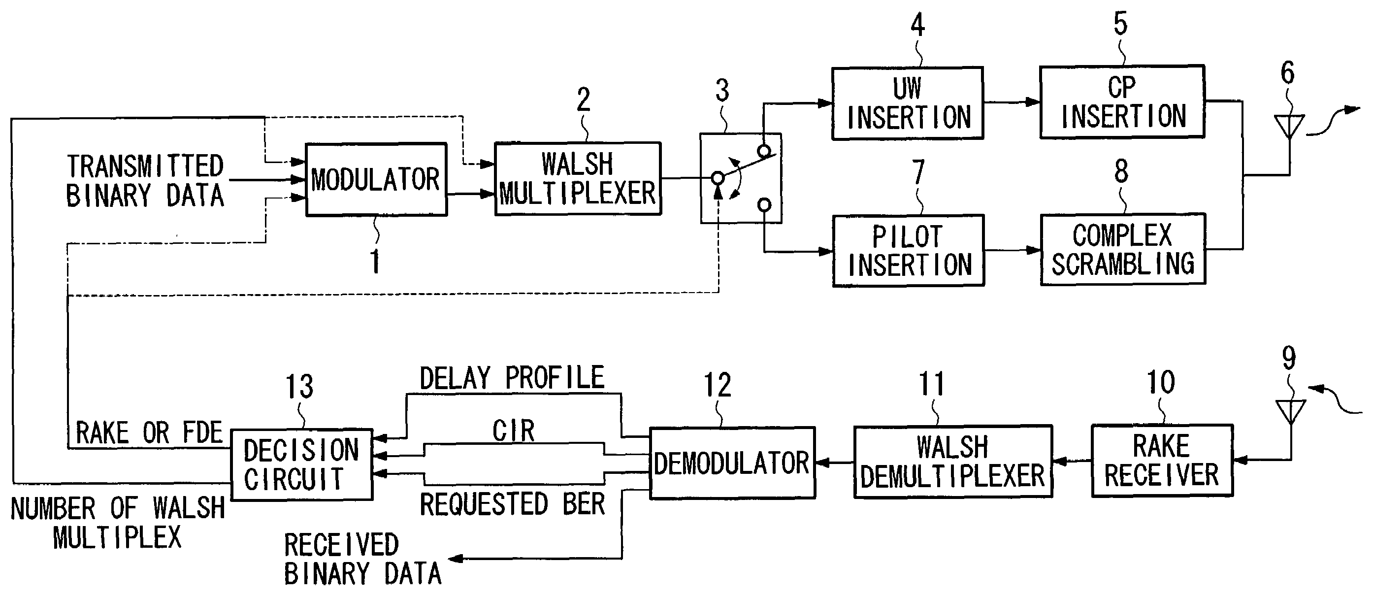
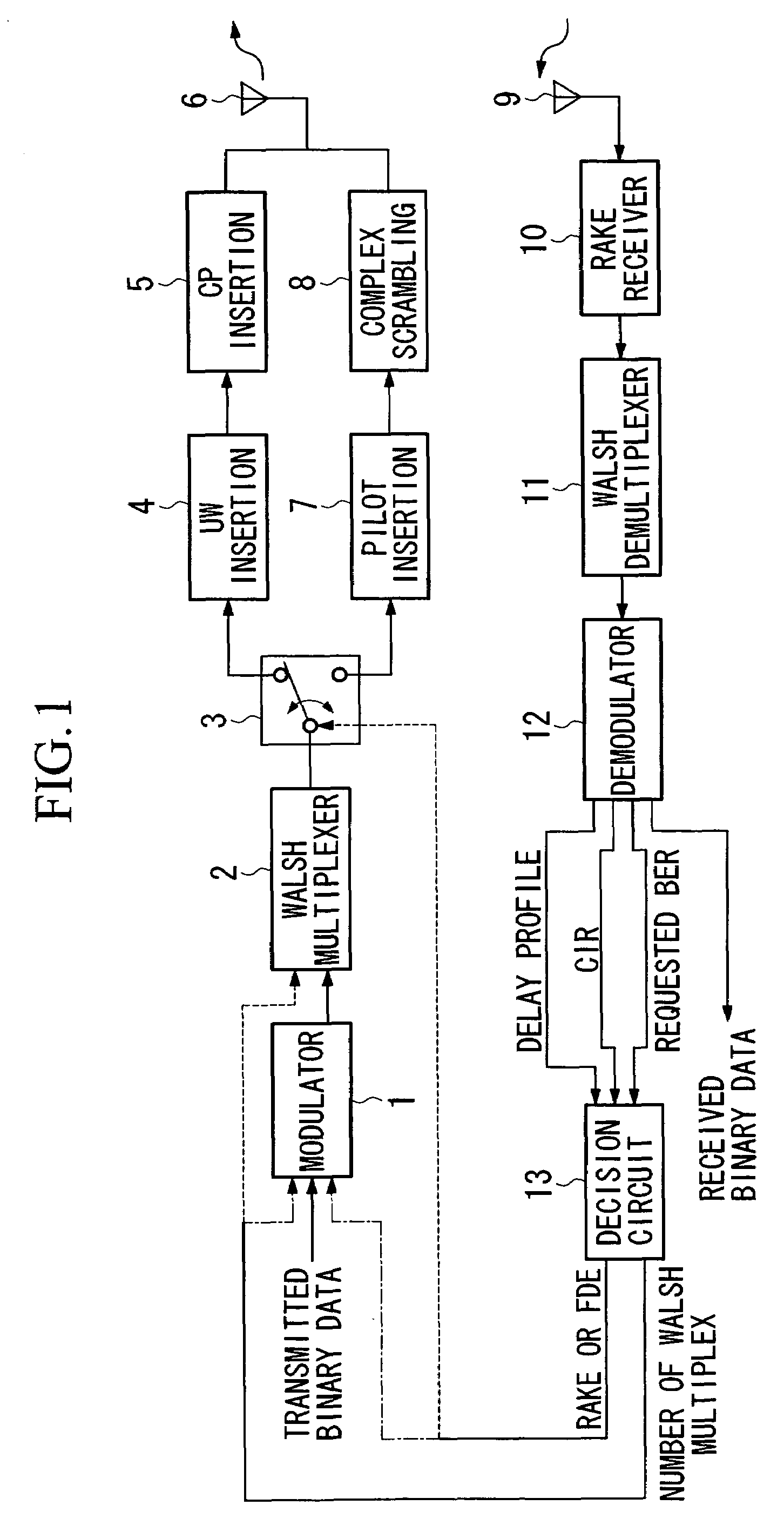
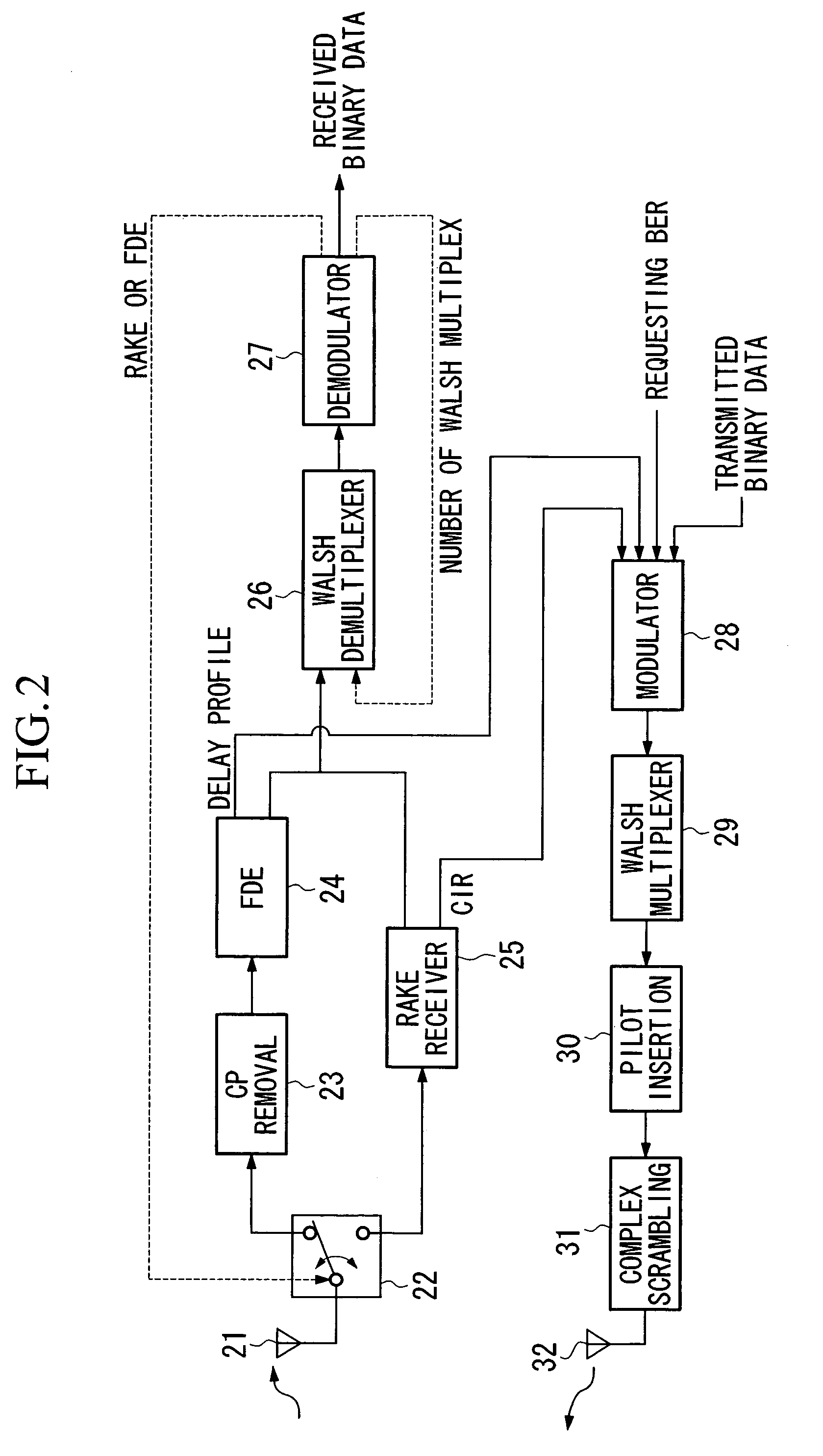
[0058]FIGS. 1 and 2 are block diagrams showing examples when the transmitter and receiver of the first embodiment of the present invention are applied to the wireless communication of a down link between a base station and a mobile unit. FIG. 1 is a block diagram showing the structure of a base station provided with the transmitter of the present embodiment, while FIG. 2 is a block diagram showing the structure of a mobile unit provided with the receiver of the present embodiment.

[0059]Firstly, the base station provided with the transmitter of the present embodiment will be described using FIG. 1.

(Base Station Transmitter)

[0060]In FIG. 1, a modulator 1 indicates transmitted binary data and control signals and the like that are transmitted from a base station to a mobile unit. Output signals from the modulator 1 are input into a Walsh multiplexer 2. The Walsh multiplexer 2 multiplexes signals using code division multiplexing based on Walsh code in accordance with a transmission rate ...

second embodiment

[0138]The transmitter and receiver of the second embodiment of the present invention will be described.

[0139]FIGS. 8 and 9 are block diagrams showing the application of the transmitter and receiver of the second embodiment of the present invention to down link communication from a base station to a mobile unit. FIG. 8 is a block diagram showing the structure of a base station provided with the transmitter of the present embodiment, while FIG. 9 is a block diagram showing the structure of a mobile unit provided with the receiver of the present embodiment.

[0140]The transmitter and receiver of the present embodiment differ from the transmitter and receiver described in the first embodiment in that the existence or otherwise of code division multiplexing for signals transmitted by the transmitter and also the number of Walsh multiplex are decided by a mapping circuit using the reception quality that includes a delay profile and CIR measured on the receiver from the received signals, and...


PUM


Abstract

A receiver informs a delay profile and CIR measured in an FDE or a Rake receiver, together with a bit error rate of a received signal that is required in a receiver, as quality information to a transmitter. In the transmitter, based on the delay profile and CIR contained in the notified quality information, a number of code division multiplex and a frame format are decided in a decision circuit such that a bit error rate of a received signal, which is necessary on the receiver side, can be obtained. In addition, a transmission selection switch selects one of a unique word insertion unit and a cyclic prefix insertion unit that create a frame format for FDE reception and a pilot insertion unit and a complex scrambling unit that create a frame format for Rake reception, and data is then transmitted.

Description

BACKGROUND OF THE INVENTION[0001]Priority is claimed on Japanese Patent Application No. 2003-039894, filed Feb. 18, 2003, the content of which is incorporated herein by reference.[0002]1. Field of the Invention[0003]The present invention relates to a transmitter and a receiver that transmit and receive signals.[0004]2. Description of Related Art[0005]Mobile communication is fundamentally communication beyond the line of sight, and multipath channel is formed by reflection, diffraction, and scattered waves. Furthermore, when the delay time of each path is too large to be disregarded, a multipath channel having delay diffusion. In a multipath channel having delay diffusion, the channel behaves like a particular type of filter and, as a result, transmitted signals thereof receive frequency selective fading (see, for example, “Modulation and De-modulation in Digital Wireless Communication”, by Youichi Satoh, published by the Electronic Information Communication Society 1996, pp. 157-158...

Claims


Application Information

Patent Timeline
IPC IPC(8): H04L27/00H04B1/707H04B1/711H04B7/26H04J11/00H04J13/18H04W28/06H04W28/18H04W72/04H04W72/08
CPCH04B1/7097H04B2201/70701
Inventor MIYAZAKI, NORIAKISUZUKI, TOSHINORI
Owner KDDI CORP
Why Eureka
Try Eureka