
Wireless receiver apparatus provided with gain control amplifier

a receiver and gain control technology, applied in the direction of amplifiers, electrical devices, semiconductor devices/discharge tubes, etc., can solve the problems of deterioration in the conversation quality and the rate (ber) deterioration, and achieve the effect of preventing the deterioration in the signal quality and good conversation quality

Active Publication Date: 2011-04-05
PANASONIC SEMICON SOLUTIONS CO LTD
View PDF11 Cites 1 Cited by
  • Summary
  • Abstract
  • Description
  • Claims
  • Application Information

AI Technical Summary

Benefits of technology

The present invention provides a wireless receiver apparatus and a semiconductor integrated circuit that can maintain good conversation quality by preventing signal quality degradation during switching of the gain control amplifier. The wireless receiver apparatus includes a maintaining device for keeping the gain of the reception signal at a predetermined fixed value only in a predetermined specified interval. The start and end timings of the specified interval are determined based on a predetermined timer start and timer reset signal, respectively. The wireless receiver apparatus also includes a selecting device for selecting between predetermined control signals to set the timer start or timer reset signal. The semiconductor integrated circuit includes the wireless receiver apparatus integrated with other components. The technical effect of the invention is to improve the quality of wireless communication by preventing signal quality degradation during switching of the gain control amplifier.

Problems solved by technology

Even when the constant of the hold capacitor 301 of the prior art is optimized, the gain of the gain control amplifier is disadvantageously varied for the interval of the real data part at an input level in the vicinity of the field strength with which the gain of the gain control amplifier 103 varies, and the bit error rate (BER) deteriorates as shown in FIG. 4, and this leads to deterioration in the conversation quality.

Method used


Image

  • Wireless receiver apparatus provided with gain control amplifier
  • Wireless receiver apparatus provided with gain control amplifier
  • Wireless receiver apparatus provided with gain control amplifier

Examples


Embodiment Construction

[0041]Embodiments of the present invention will be described with reference to the drawings. In each of the following embodiments, similar components are denoted by like reference numerals.

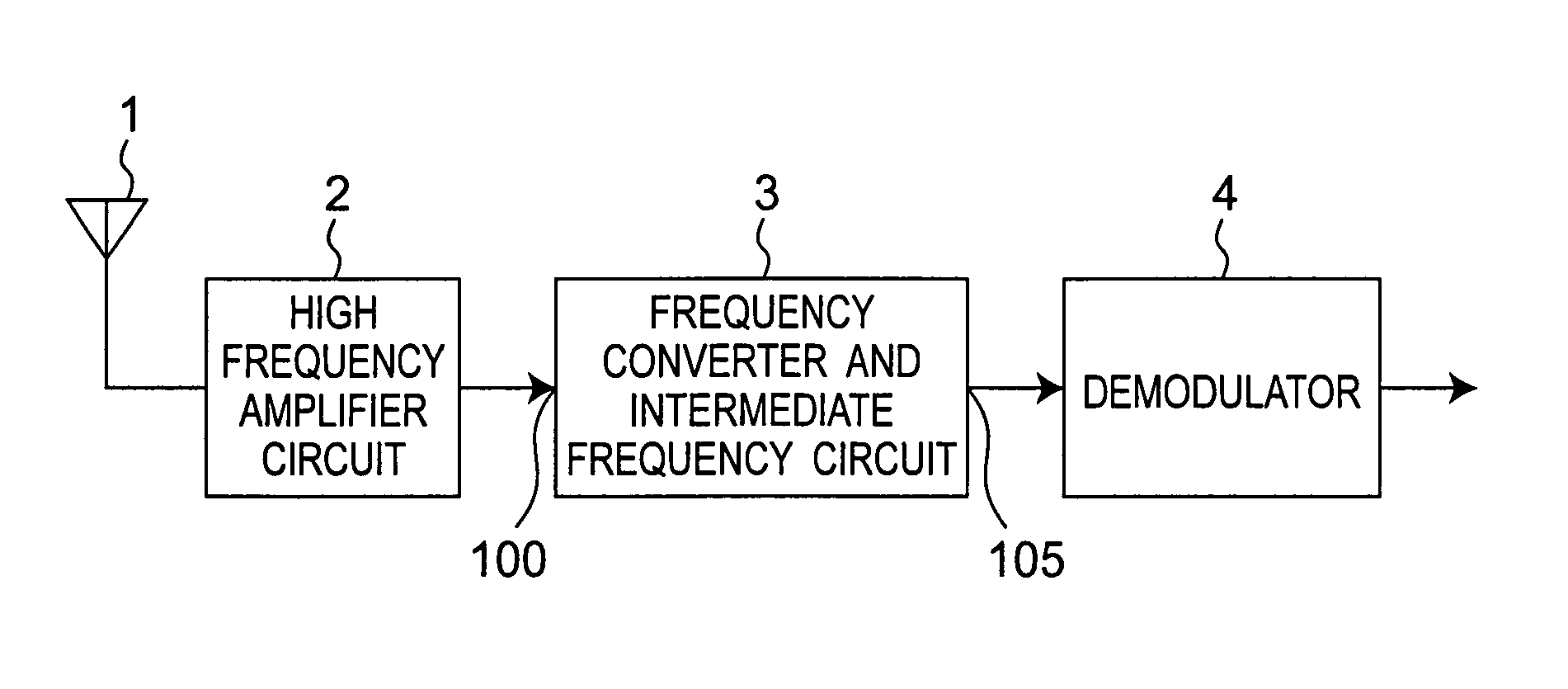
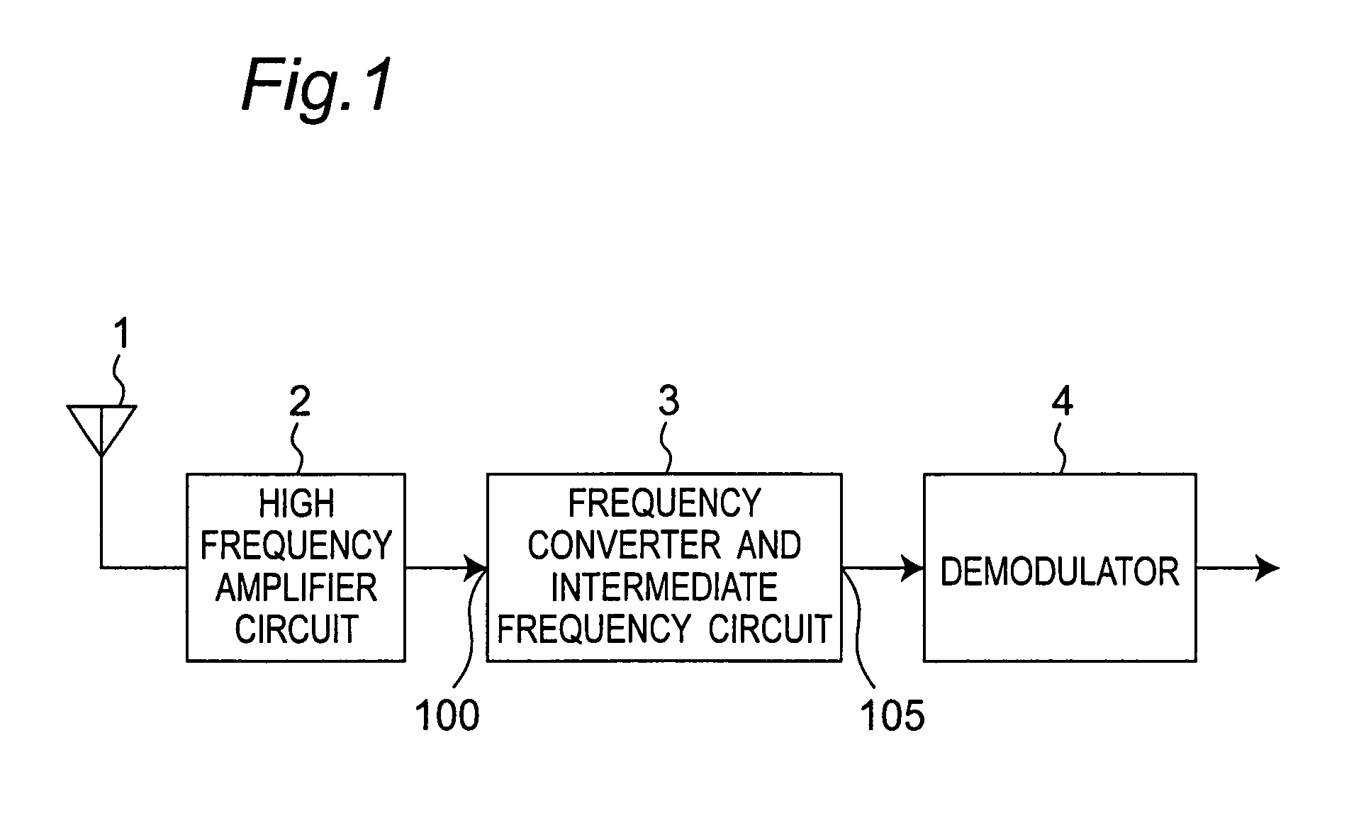
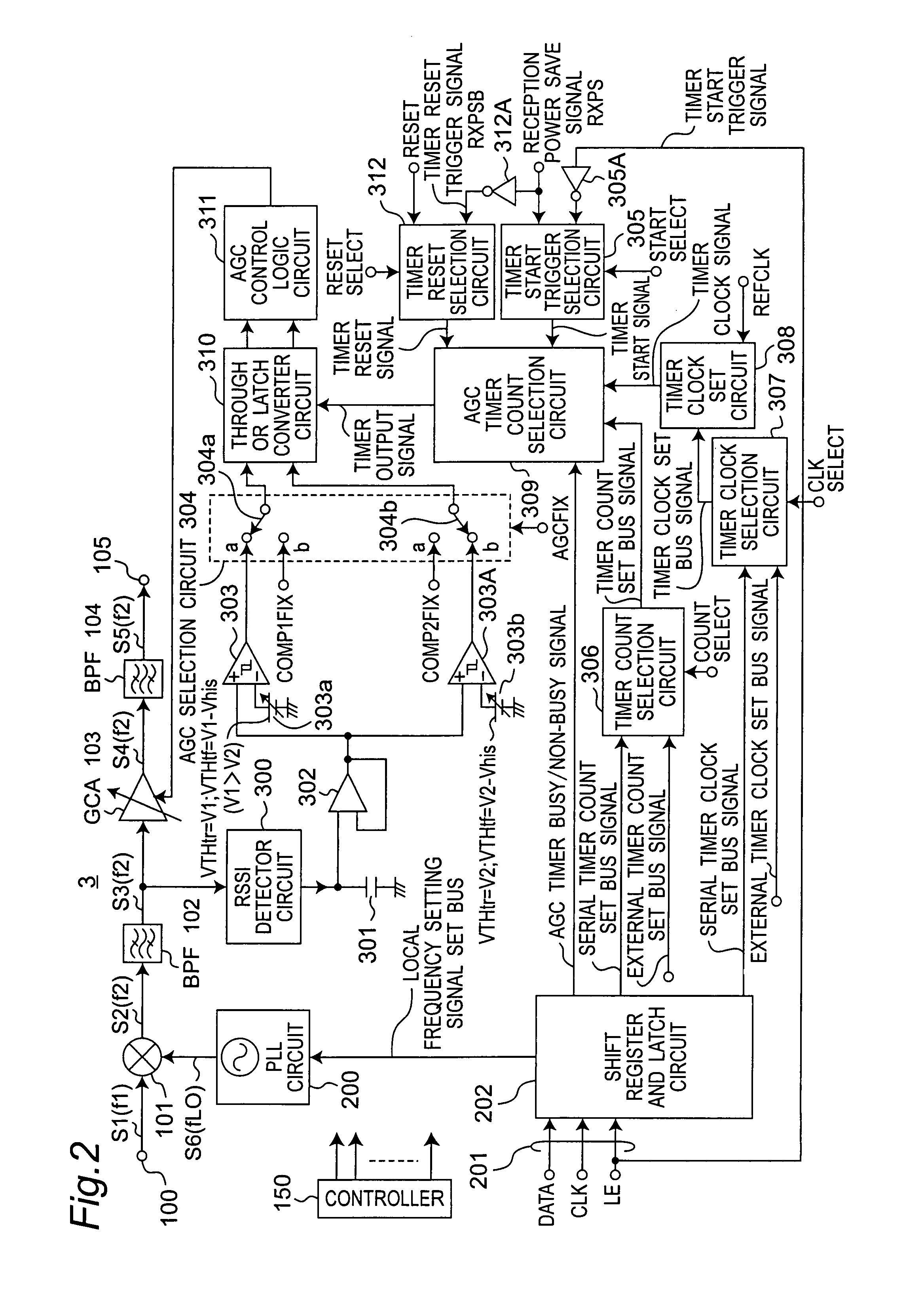
[0042]FIG. 1 is a block diagram showing a configuration of a wireless receiver apparatus according to an embodiment of the present invention, and FIG. 2 is a block diagram showing a configuration of the frequency converter and intermediate frequency circuit 3 of FIG. 1. As shown in FIG. 1, the wireless receiver apparatus of the present embodiment is configured by including an antenna 1, a high frequency amplifier circuit 2, the frequency converter and intermediate frequency circuit 3, and a demodulator 4. A wireless signal received by the antenna 1 is low-noise-amplified by the high frequency amplifier circuit 2, and then, it is inputted to the frequency converter and intermediate frequency circuit 3. It is herein noted that an alternative configuration may be used, in which the output signal from...


PUM


Abstract

In a wireless receiver apparatus including a gain control amplifier for controlling a gain of a reception signal, a maintaining device compulsorily maintains the gain of the gain control amplifier at a predetermined fixed value only in a predetermined specified interval. The maintaining device includes a latch circuit for maintaining a gain set value immediately prior to the specified interval. A start timing of the specified interval is determined by an edge of a predetermined timer start signal, and a duration of the specified interval is determined on the basis of a count of a predetermined timer clock signal and a count of a predetermined timer count set bus signal.

Description

BACKGROUND OF THE INVENTION[0001]1. Field of the Invention[0002]The present invention relates to a wireless receiver apparatus, and in particular, to a wireless receiver apparatus including a gain control amplifier (GCA), and a semiconductor integrated circuit which is formed by integrating a circuit of the wireless receiver apparatus.[0003]2. Description of the Related Art[0004]FIG. 9 is a block diagram showing a configuration of a wireless receiver apparatus used in, for example, a wireless communication system of a personal handy-phone system (hereinafter referred to as PHS) according to a prior art, and FIG. 10 is a block diagram showing a configuration of a frequency converter and intermediate frequency circuit 3A of FIG. 9.[0005]Referring to FIG. 9, the wireless receiver apparatus of the prior art is configured by including an antenna 1, a high frequency amplifier circuit 2, the frequency converter and intermediate frequency circuit 3A and a demodulator 4. A wireless signal re...

Claims


Application Information

Patent Timeline
Patent Type & Authority Patents(United States)
IPC IPC(8): H04B7/00H04B1/06H03G3/20H04B1/16
CPCH03G3/3078
Inventor TAKAHASHI, KOUJIOTA, KOSUKE
Owner PANASONIC SEMICON SOLUTIONS CO LTD
Learn More