
System and method for verifying delay time using mobile image terminal

a mobile terminal and delay time technology, applied in the field of mobile terminals, can solve the problems of inability to quantitatively measure the delay time between two terminals in a real-time image telecommunication system, and no tool capable of monitoring in real-time the delay tim

Inactive Publication Date: 2005-09-22
LG ELECTRONICS INC
View PDF6 Cites 24 Cited by
  • Summary
  • Abstract
  • Description
  • Claims
  • Application Information

AI Technical Summary

Benefits of technology

[0016] An object of the present invention is to provide a system and a method for verifying a delay time between mobile image terminals capable of quantitatively measuring a data delay time generated during an image call between image telephone terminals.
[0018] A further another object of the present invention is to provide a system and a method for verifying a delay time between mobile image terminals capable of improving image call quality even more on the basis of data delay information between mobile image terminals using a monitoring device.
[0022] According to the present invention, time information generated at data transmission point and time information generated when the same data is received again are monitored in real-time using two terminals and one monitoring device, whereby the data delay time information can be measured and better image telecommunication service can be provided on the basis of such information.

Problems solved by technology

However, it is impossible to quantitatively measure an image delay time between two terminals in a real-time image telecommunication system.
Also, there is no tool capable of monitoring in real-time a measured delay time.

Method used


Image

  • System and method for verifying delay time using mobile image terminal
  • System and method for verifying delay time using mobile image terminal
  • System and method for verifying delay time using mobile image terminal

Examples


Embodiment Construction

[0031] Reference will now be made in detail to the preferred embodiments of the present invention, examples of which are illustrated in the accompanying drawings.

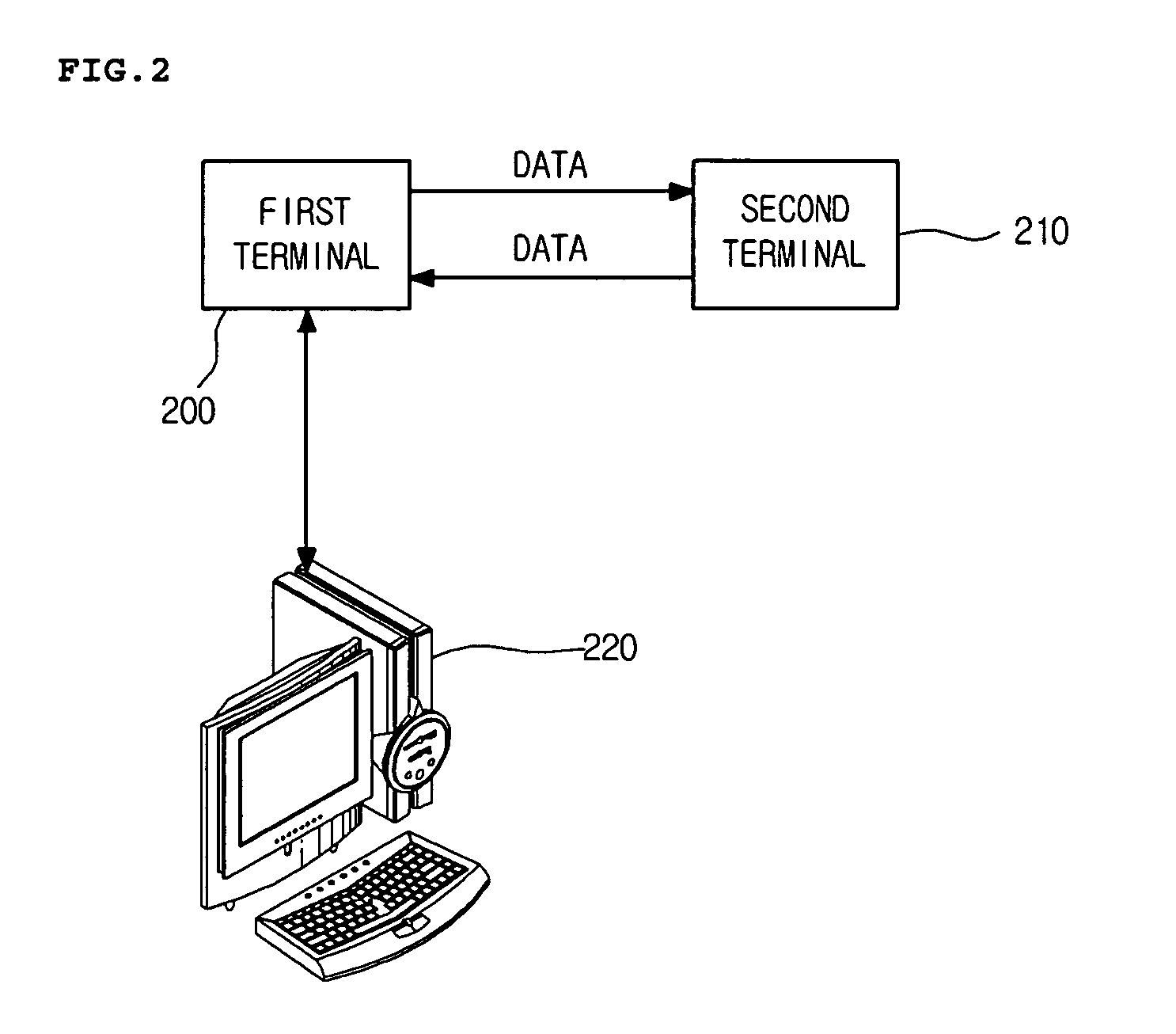
[0032]FIG. 2 is a block diagram of a system for verifying a delay time between mobile image terminals according to a preferred embodiment of the present invention.

[0033] Referring to FIG. 2, the system includes: a first terminal 200 for transmitting / receiving data for an image call and measuring a delay time of data being looped back; a second terminal 210 for re-transmitting the data received from the first terminal 200 to the first terminal 200; and a monitoring device 220 for outputting delay time information measured by the first terminal 200.

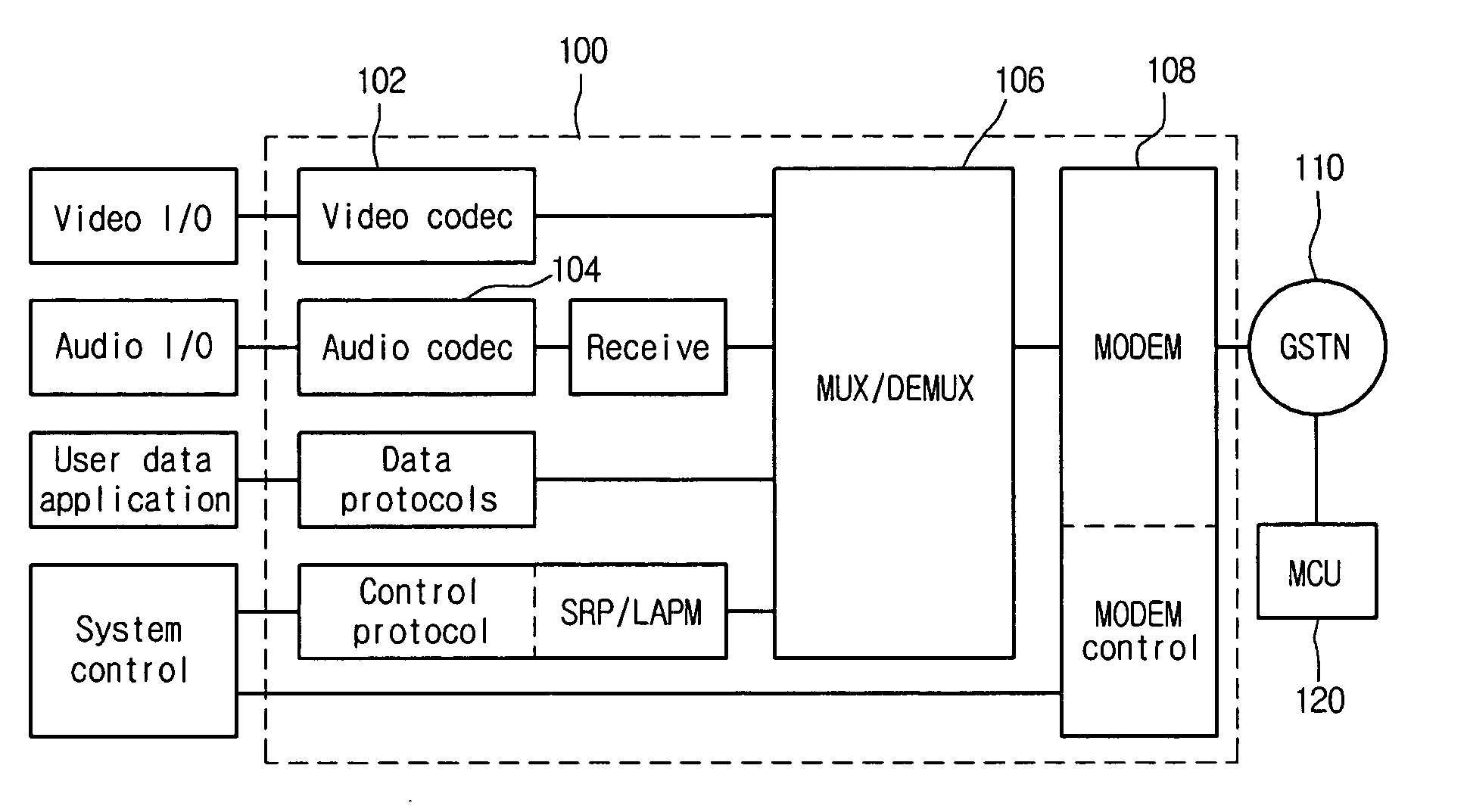
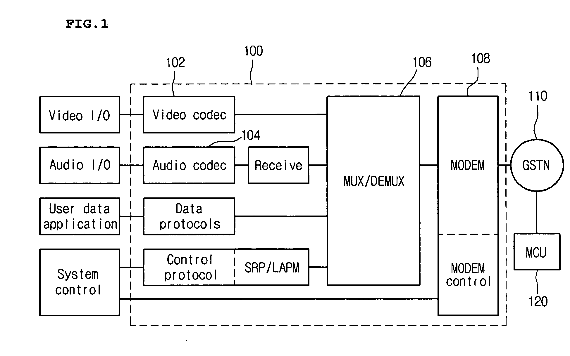
[0034] The data transmitted by the first terminal 200 includes audio data, video data, and control data. The data is multiplexed by a multiplexer and transmitted.

[0035] The first terminal 200 is connected with the second terminal 210 for an image call through a wireless network...


PUM


Abstract

The present invention relates to a mobile terminal, to a system and a method capable of monitoring in real-time a delay time of data transmitted / received between terminals in mobile terminals. According to the method, a terminal at a transmission side encodes data for an image call, transmits the encoded data to a terminal at a reception side, and receives the transmitted data as a loop-back to decode the same. An external monitoring device measures delay time information of the data using encoding and decoding time information and displays the information on a screen.

Description

BACKGROUND OF THE INVENTION [0001] 1. Field of the Invention [0002] The present invention relates to a mobile terminal, and more particularly, to a system and a method capable of monitoring in real-time a delay time of data transmitted / received between terminals in mobile terminals. [0003] 2. Description of the Related Art [0004] A recent mobile telephone terminal has a camera for its indispensable element to provide a user with image communication service that uses voice and an image as well as communication service that uses voice. [0005] For transmission of moving image information containing multimedia data on a mobile communication channel, image data, audio data, and control data are multiplexed and transmitted. International Telecommunications Union—Telecommunication Standardization Sector (ITU-T) H.324 multimedia terminal standard generally prescribes mobile image telecommunication under a circuit-switched environment. [0006] H.324 is a protocol of an image telephone and a t...

Claims


Application Information

Patent Timeline
Patent Type & Authority Applications(United States)
IPC IPC(8): H04M1/00H04N7/14H04N7/15
CPCH04N7/152H04N7/148G06F15/163H04N21/43615H04N21/43637H04N21/2343H04W84/12G06F2213/0024
Inventor KIM, JOO MIN
Owner LG ELECTRONICS INC
Learn More